Tubular tower
-
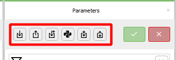
 import a text file. The format of the text file is explained in the
Support section files section
import a text file. The format of the text file is explained in the
Support section files section -
 export the text file corresponding to the current tubular tower
-
 import a file containing a load history. The format of the file is explained in the
Load history file section
import a file containing a load history. The format of the file is explained in the
Load history file section -
 applied loads calculated with a python script. More details are given in Section 2 of the
Support structure document
applied loads calculated with a python script. More details are given in Section 2 of the
Support structure document -
 import a Craig-Bampton superelement
-
 export the mass, damping and stiffness matrices
General
Input file
The file to be imported to generate the support section. Import (in batch) by pressing the 'Import a support section from file' button in the action button collection to the right. This parameter (and this text) can only be visible in the batch (and not anywhere in the Time simulation window).
To import a support section in the Time simulation window, the ' Import a support section from file ' action button must be used. Correspondingly, a support section can be exported to file in the time simulation window by using the ' Export the support section to file ' action button. In batch the same buttons are placed to the right of the 'normal' parameters.
If the file is changed, moved, or removed after the import this will not affect the support section. For a change in the file to be effective the file must be imported again.
- Default value:
- Unit: —
Scaling scheme
Scheme for scaling of this support section only (i.e. not the complete support structure - the complete support structure can be scaled on the Support structure part).
This parameter is only shown if the Wind turbine's 'Scaling scheme' parameter is set to ' Local scaling '.
A support section imported from file cannot be scaled. Thus, this parameter is never shown if the support section is imported from file.
Options:
Parent (default):
The scaling factor is set equal to the scaling factor for the whole Support structure.
Override:
A scale factor (set by you) for this section only (i.e. the scale factor set for the support structure is overridden).
Scaling factor
The geometry of this section of the support structure defined by parameters and/or files will be scaled by this factor.
- Default value: 1
- Unit: —
- Range: 0.001 — 1000
Height
The height of this section of the support structure. The height also takes into consideration any part below the seabed/ground, e.g. the piles on a truss tower.
If the height is set so low that the top of the section is below the sea surface, the set height is overruled and increased automatically so that the top is at the surface.
- Default value: 100
- Unit: $\text{m}$
- Range: 1 — 1000
Material
The material used for this sub section of the support structure.
- Default value: Steel
- Unit: —
Maximum element length
The maximum length a generated frame element can have, i.e. the elements will have this length or shorter.
- Default value: 5
- Unit: $\text{m}$
- Range: 0.01 — 1000
Load histories file
The file adds load (time) histories to one or more nodes of the support section. The node names in the file must be found in the support section. The history can either be a force or moment history. If it is a moment history, the node name must be followed by any other string than 0 (i.e. the line contains two strings). An example of a load histories file can be found in the Examples folder. Open it from the menu: Help | Open examples folder. Make a copy of this file and then adapt it to the support section.
Note: A load histories file can only be used when the support section has been imported from file. You can right-click the support section and select Export to file to create a file that you can import again (by right-clicking the support section).
- Default value:
- Unit: —
Loads script file path
The file path to the external script for support section loads, i.e. to the .py file.
- Default value:
- Unit: —
Geometry
Shape
The shape of the tubular tower. Can be 'Tapered' or 'Cylindrical'.
Options:
Tapered (default):
Both the diameter and the thickness of the circular hollow cross section change along the height.
Cylindrical:
The outer diameter and the thickness of the circular hollow cross section is constant along the hieght og the tubular tower.
Top diameter
The outer diameter of the tubular tower at the top.
- Default value: 3.87
- Unit: $\text{m}$
- Range: 0.01 — 100
Top thickness
The thickness at the top of the tubular tower. If the thickness is set to greater than half the diameter it is reduced to half the diameter.
- Default value: 0.025
- Unit: $\text{m}$
- Range: 0.001 — 10
Base diameter
The outer diameter of the tubular tower at the bottom.
- Default value: 6
- Unit: $\text{m}$
- Range: 0.01 — 100
Base thickness
The thickness of the tubular tower at the base (thickness of the circular hollow cross section). The thickness of the tubular tower between the base and the top is interpolated. If the thickness is set to greater than half the diameter it is reduced to half the diameter.
- Default value: 0.035
- Unit: $\text{m}$
- Range: 0.001 — 1
Transition piece
Has transition piece
If checked, the bottom part of the tubular tower is made into a transition piece. The transition piece is circular with constant diameter and thickness.
A tubular tower can have a transition piece (TP) at its lower part. However, onshore WTs typically don't have a TP - this design choice is more common for offshore bottom-fixed WTs. If you want to model a TP with different geometry and/or stiffness/mass properties than allowed by the parameters here (i.e. circular hollow), then it must be modelled in a text file and imported.
Note: A parameterized truss tower also has a transition piece connecting the upper point of its legs to the start point of a tubular tower or an RNA on top of the truss tower.
- Default value: False
- Unit: —
Mass
Mass added to the upper node of the transition piece, i.e. the node connecting the transition piece to the tubular tower above it. The total mass of the transition piece is thus its structural mass plus this mass.
- Default value: 66600
- Unit: $\text{kg}$
- Range: 0 — 100000
Height
The height of the transition piece (TP). This height is NOT added to the height of the the tubular tower itself. The height can be max 70% of the (total) height of tubular tower. If it is set to a greater value it is auto-corrected to 70%.
- Default value: 4
- Unit: $\text{m}$
- Range: 0.1 — 100
Diameter
The cross-sectional outer diameter of the hollow circular member making up the transition piece (TP) of the tubular tower.
- Default value: 7
- Unit: $\text{m}$
- Range: 0.01 — 10
Thickness
The cross-sectional thickness of the hollow circular member making up the transition piece(TP).
The thickness cannot be greater than the half of the outer diameter. If it is set to a greater value, then it is auto-corrected to half.
- Default value: 0.4
- Unit: $\text{m}$
- Range: 0.001 — 1
Loads
Can have hydro loading
If this is not checked, the tubular tower cannot have hydrodynamic loading (not even with 0 value), no matter what settings on other parameters.
- Default value: False
- Unit: —
Potential flow
WAMIT .1 table
The WAMIT .1 table defined in the .1 file. Note that Ashes assumes each column has a column title on the first row, modify your files so they have column titles.
- Default value:
- Unit: —
WAMIT .1 table file path
The file path to the WAMIT .1 table. Only used in batch. If set, the WAMIT .1 table is imported from this file.
- Default value:
- Unit: —
WAMIT .3 table
The WAMIT .3 table defined in the .3 file. Note that Ashes assumes each column has a column title on the first row, modify your files so they have column titles.
- Default value:
- Unit: —
WAMIT .3 table file path
The WAMIT .3 table file path. Only used in batch. If set, the WAMIT .3 table is imported from this file.
- Default value:
- Unit: —
2nd order PF model
Selects the second-order potential flow model to be used for computing second-order wave forces.
Options:
None (default):
No second-order potential flow forces will be computed.
Newman's approximation:
Second-order forces will be computed using Newman's approximation method based on the WAMIT .12D table data.
Mean drift forces:
Mean drift forces will be computed using WAMIT .8 file data for diagonal QTF terms.
WAMIT .12D table
The WAMIT 12D table defined in the .12D file. Note that Ashes assumes each column has a column title on the first row, modify your files so they have column titles.
- Default value:
- Unit: —
WAMIT .12D table file path
The WAMIT .12D table file path. Only used in batch. If set, the WAMIT .12D table is imported from this file.
- Default value:
- Unit: —
WAMIT .8 table
The WAMIT .8 table defined in the .8 file for mean drift force computation. Note that Ashes assumes each column has a column title on the first row, modify your files so they have column titles.
- Default value:
- Unit: —
WAMIT .8 table file path
The WAMIT .8 table file path. Only used in batch. If set, the WAMIT .8 table is imported from this file.
- Default value:
- Unit: —
Characteristic length
The characteristic length used to compute potential flow loads.
- Default value: 1
- Unit: —
- Range: 0 — 1e+08
Apply to node option
Specifies if the potential flow loads should be applied to the node closes to center-of-mass, or if the node is specified by the user.
Options:
Node closest to center-of-mass (default):
The loads will be applied to the node closest to the center-of-mass.
User-defined:
The node is specified by the user.
Node name
The name of the node where potential flow loads are to be applied. The name does not include the word "Node", but rather the string after "Node" (which can be a number but also just text). You can find a node's name by right-clicking the structure.
- Default value:
- Unit: —