Benchmarks from Irgens (1985)
In this document we compare results produced by Ashes to results published in the structural analysis book by
Irgens (1985). In this book, several examples provide numerical benchmarks for different types of beams, supports and load conditions.
1 Benchmarks
Two benchmarks from
Irgens (1985) are used for this test, presented in the two subsections below. For each benchmark, the simulation is run using the
Linear and the
Non-linear solvers (see
Time domain simulation). This will produce 4 sets of results.
1.1 - Example 1 Chapter 19
This example considers a cantiliever I-beam of length
$$L = 4\text{ m}$$
, Elastic modulus
$$E = 210\cdot10^9\text{ Pa}$$
and second moment of inertia
$$I =4.75\cdot10^{-5}\text{ m}$$
. A point load
$$F = 20\text{ kN}$$
is applied at the free end of the beam. This example does not take
Shear deformation into account and can therefore be modeled with Euler-Bernoulli beams.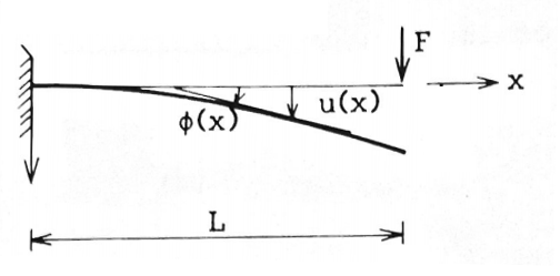
According to
Irgens (1985), this yields a maximum displacement at the tip of the beam
$$u_{max}=\frac{FL^3}{3EI}=0.043\text{ m}$$
and a maximum rotation
$$\phi_{max}=\frac{FL^2}{2EI}=0.92\text{ degrees}$$
1.2 - Example 3 Chapter 19
This example considers an I-beam simply supported on both ends (i.e. with a pinned support on both ends). The beam has a length
$$L = 7\text{ m}$$
, an Elastic modulus
$$E = 210\cdot10^9\text{ Pa}$$
and a second moment of inertia
$$I=8.36\cdot10^{-5}\text{ m}$$
. A distributed load
$$q=9400\text{ N}\cdot\text{m}^{-1}$$
is applied on the beam. This example does not take
Shear deformation into account and can therefore be modeled with Euler-Bernoulli beams.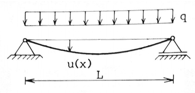
According to
Irgens (1985), this yields a maximum displacement at the middle of the beam
$$U_{max}=\frac{5}{384}\frac{qL^4}{EI}=0.0168\text{ m}$$
Note: This test is run in two ways: 1) applying gravity loads and setting the mass to obtain the correct loading and 2) disabling gravity loads and applying the correct external loading using a
Load history file. The results from the two simulations is expected to be the same.
1.3 Example 5 Chapter 24
This example considers an angle beam (or L-beam) supported on one end and with a load on the other end, as shown in the figure below:
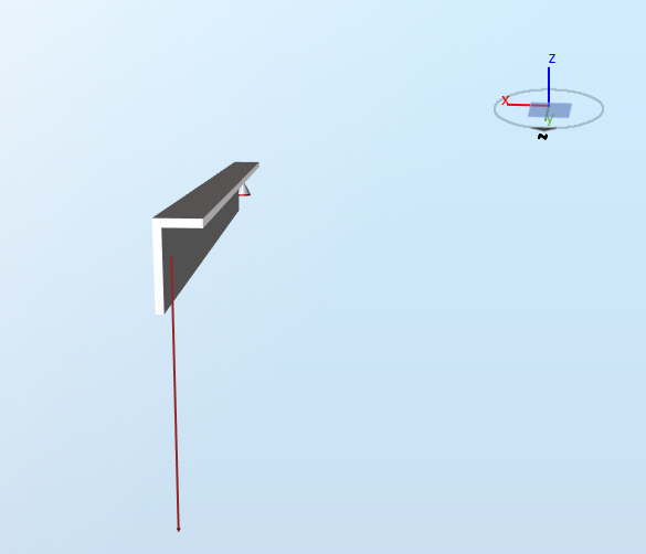
The length of the first and second legs are
From Irgens (1985), the second moment of inertia about the first and second legs are
$$L_1 = 0.105\text{ m}$$
and
$$L_2 = 0.055\text{ m}$$
, respectively, and the thickness is
$$t=0.010\text{ m}$$
.
From Irgens (1985), the second moment of inertia about the first and second legs are
$$I_1 = 3.125\cdot10^{-7}\text{ m}^4$$
and
$$I_2 = 1.667\cdot10^{-6}\text{ m}^4$$
. The product moment of inertia is
$$I_{xy}=-4.167\cdot10^{-7}\text{ m}^4$$
.
Note: the values for the moment of inertia given by
Irgens (1985) do not match those computed by online calculators or by Ashes. It is not clear how the moments of inertia are derived in
Irgens (1985), but in this test we use their values in order to benchmark the displacements.
The Elastic modulus of the material is
$$E = 70\cdot10^9\text{ Pa}$$
.
According to
Irgens (1985), the expected displacements at the tip of the beam in the z- and x-direction are
$$d_x = 0.0114\text{ m}$$
and
$$d_z = -0.0086\text{ m}$$
2 Results
The test is considered passed when the last 20% of the Ashes time series lies within 1% of the benchmark value.
The report for this test can be found on the following link:
Note: for the dynamic simulations in Ashes, the loads are ramped-up from 0 to their value in 15 seconds. It is therefore expected that the results from Ashes do not match the benchmark values for the first 15 seconds (See
Loads ramp-up tab in the
Analysis section.