Simulation window
1 Overview
From the
Starting window, open the onshore template, the following window will appear on your screen.
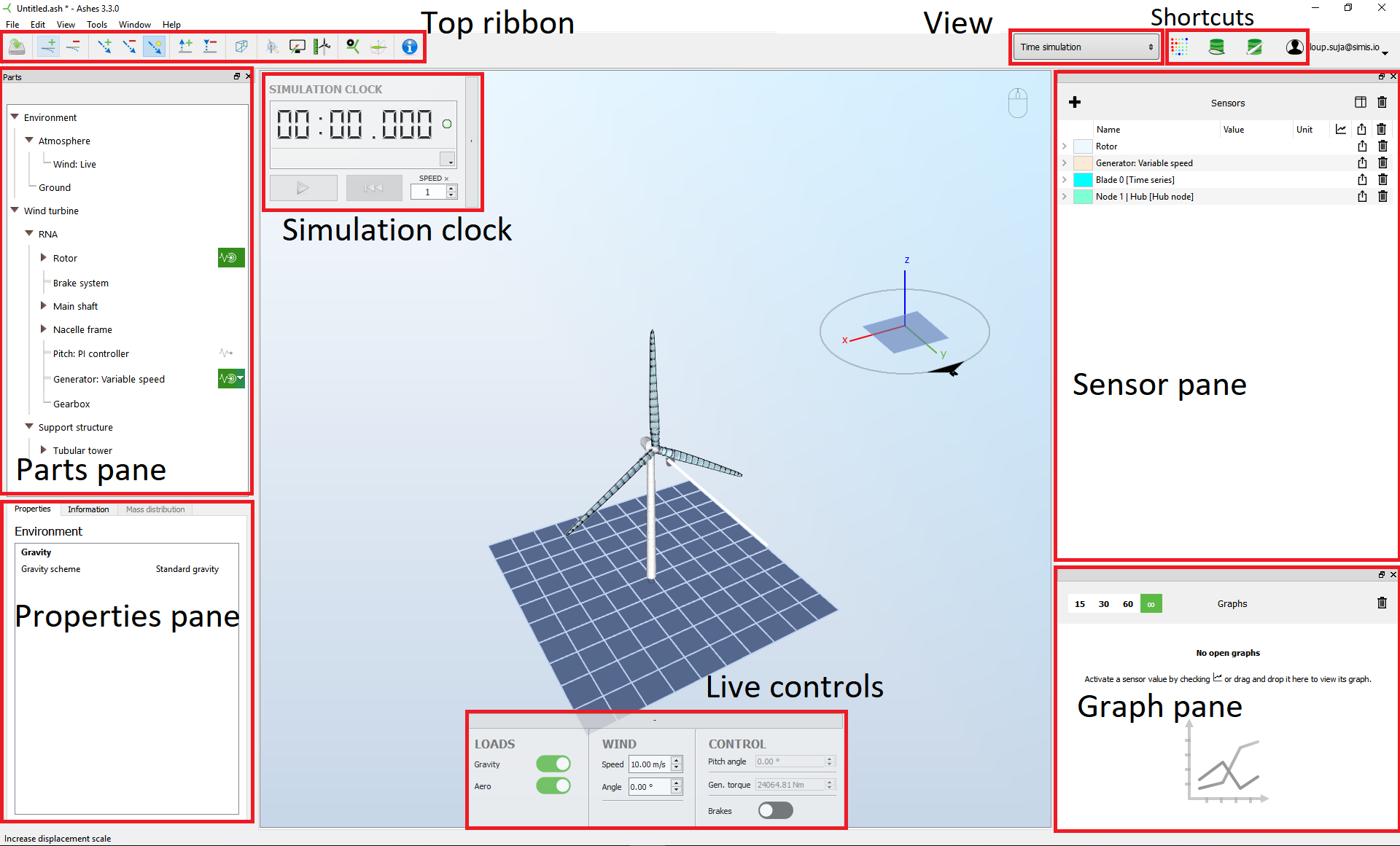
Your model appears in the center of the window, and the rest of the screen is divided into different sections with different functionalities, listed below.
2 Tool tip
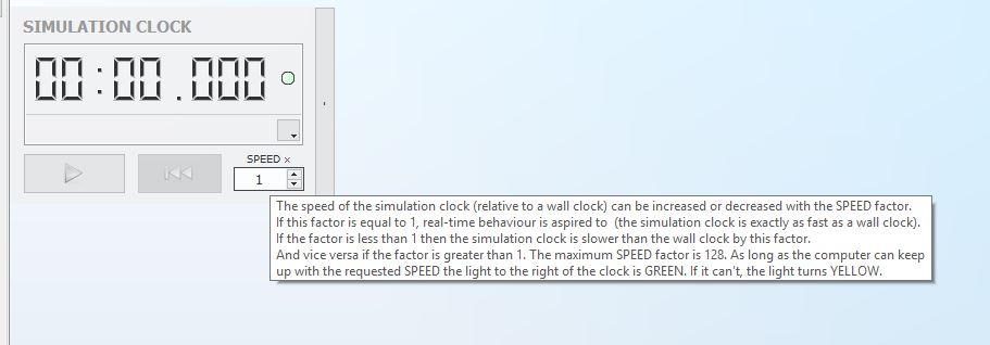
Most items in Ashes (parameter, sensor, button...) come with a
tool tip, a little box with text that explains what the item does. Just hover the mouse over the item for a second and the tool tip will appear. The image below shows the tool tip for the speed factor in the simulation clock.
3 Simulation clock
The simulation clock enables you to start, pause and reset the simulation. The simulation speed can be changed with the
speed
factor: if you want to speed up the simulation to reach a certain point in time you can increase the speed factor, if you need to slow down the simulation to check some details of the simulation you can decrease the speed factor.
Note that the simulation itself will not be affected by the speed factor, which means that the accuracy of the results are independent of this parameter. If you request a high speed factor, your computer might not be powerful enough, in which case the simulation will run at the highest speed allowed by your computer.
A light next to the clock indicates the status of the simulation:
-
green: the simulation is running at the requested speed
-
yellow: the computer cannot keep up with the requested speed
- red: an error occured during the simulation. Clicking on the warning sign that appears then will give you more information on the error.
4 Parts pane
This pane contains the definition of the structure of the model and the environmental conditions. Clicking on any of the parts in the tree will give you access to the parameters of that part, which can be changed in the
properties pane. A list of all the parameters is given in the
Parts
5 Properties pane
The parameters for a given part will be showed here. If any change is made to these parameters, the model will be automatically updated (if a simulation was running when you change the parameters you will be asked to reset the model).
All the parameters in this pane have a tool tip that explain what they do and how to use them.
6 Live controls
The
live controls
enable you to change some parameters while the simulation is running, i.e. without the need to reset the simulation. The parameters available in the live control change depending on the model that you are using (for example, you will be able to change the wave conditions only on offshore or floating models).
In order to be able to modify a parameter live, you need to make sure that the
live
option for that parameter is selected. If for example you want to change the wind speed live, you need to select
Live wind
in the
Atmosphere part. If instead you have selected
Uniform wind, the wind parameters in the live controller will be disabled and you will have to set the wind speed in the properties of the
Uniform wind part.
7 Sensor pane
The sensors enable you to visualize and export the results produced by Ashes. Detailed information about how to use them is given in the
Sensors section.
8 Graph pane
This pane enables you to plot the outputs from the sensors.Detailed information about how to use it is given in the
Visualize the data
section.
9 Top ribbon
The top ribbon shows different icons, listed below:
-
 is a shortcut to save the model
-
 increases or decreases the deformations. This has no effect on the simulation or the outputs, it is only for visualization purposes.
-
 increases or decreases the size of the vectors representing the loads. This has no effect on the simulation or the outputs, it is only for visualization purposes.
-
 toggles on or off the visualization of the vectors representing the loads. This has no effect on the simulation or the outputs, it is only for visualization purposes.
-
 moves the camera up and down.
-
 goes to wireframe mode, where all elements are visualized as 1D rods.
-
 centers the model in your window and resets the zoom.
-
 opens the
Display settings
opens the
Display settings
. -
 opens the
Analysis parameters.
opens the
Analysis parameters.
-
 allows you to select the polar for the airfoils in the current simulation (see
Airfoil database).
allows you to select the polar for the airfoils in the current simulation (see
Airfoil database).
-
 opens a window with information about the finite element model.
10 View
The
View
dropdown menu enables you to choose from 4 simulation modes/tools, listed below.
-
Simulation window is the current window and enables you to create and visualize your model and to run time simulations.
-
Rotor characteristics enables you to plot the Cp curve of the current rotor.
-
Eigenmodes enables you to carry out an eigenmode analysis of the current structure.
11 Shortcuts
These icons can also be found in the
Starting window. They are shortcuts to some of the features of Ashes:
-
 opens the
Turbulent wind tool
opens the
Turbulent wind tool
-
 opens the
Airfoil database
opens the
Airfoil database
-
 opens the
Blade database
opens the
Blade database
-
 opens the
RNA database
opens the
RNA database
-
 gives you the possibility to log out to check your user account information. The user account is also accessible from our website at
https://www.simis.io/account/.
gives you the possibility to log out to check your user account information. The user account is also accessible from our website at
https://www.simis.io/account/.