Coordinate systems
Numerical values such as vectors and positions are given as coordinates in a Cartesian coordinate system where the right-hand rule is always followed.
The axes of coordinate systems can be shown/hidden either in
Display settings
or by selecting the relevant part or member.
1 Global Coordinate System
By default, vectors such as positions, displacement, velocities etc. have components in the
Global coordinate system. The origin of the Global Coordinate System is located at the center of the model world, at zero ground level for onshore models, or at the mean sea level (
MSL) for offshore models. The kinematics of a node (displacements, velocities and accelerations) are generally given in the Global Coordinate System
The alignment of the
Global Coordinate System
is always fixed with
- the x axis pointing East
- the y axis pointing North
- the z axis point Up
In the rest of this section, the unit vectors for these axes are noted
$$x_{global}$$
,
$$y_{global}$$
and
$$z_{global}$$
.
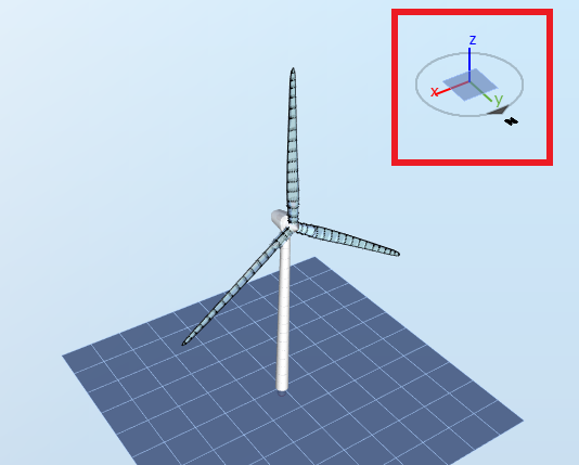
The
Global Coordinate System is shown in the upper right corner of the simulation window, as highlighted in the following picture.
2 Part Coordinate System
Structural parts, such as a support section, have each their individual local coordinate system. During a simulation, when the part becomes displaced, the
Part Coordinate System
will follow its translations and rotations.
If you don't specify any relevant settings when importing a structure, or no other setting related to the
Part Coordinate System
is changed, it will by default have its origin
fixed to the first node
of the structure and have the same initial alignment as the
Standard coordinate system
. When a part is parametrized, and not imported, the coordinate system can have a different orientation.
To view the axes of the
Part Coordinate System, open the
Display settings, go to the
Visibility
tab and tick the
Display part coordinate system box. The
Part Coordinate System will then be displayed as shown in the following picture:
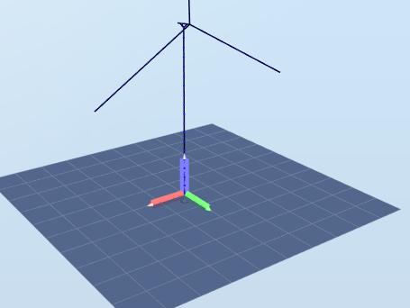
For each part, the
x axis is displayed in
red, the
y axis is displayed in
green
and the z axis is displayed in
blue. The orientation of the Part Coordinate System can be changed within the input file of the relevant support section, by modifying the
Orientation section. See the
Orientation keyword in the
Keywords section for more information.
3 Element Coordinate System
Each structural member have their own coordinate system, the
Element Coordinate System. This coordinate system is attached to the element, and follows its translations and rotations. The loads on an element, such as moment and shear forces are generally given in the element coordinate system.
The three directions that define the Element Coordinate System are named
Axial,
1
st principal and
2
nd principal
direction. An element that is defined from nodes
i to
j will have its direction defined as follows:
| Axis | Direction | Color |
|
Axial (
$$e_{axial}$$ ) |
Along the line from node i to j | Red |
|
2
nd principal (
$$e_{2}$$ ) |
$$e_{axial}\times x_{global}$$
if
$$\theta<10^{-6}$$
|
Blue |
|
$$e_{axial}\times z_{global}$$
otherwise |
||
|
1
st principal (
$$e_1$$ ) |
$$e_2\times e_{axial}$$
|
Green |
The angle θ is the angle between the axial direction of the element and z
global. In practice, this implies that
- The axial direction is always determined by the two nodes that define the element
- If the element is vertical pointing upwards (which is the case for most default templates in Ashes), the 1 st principal axis will be in the global x direction and the 2 nd principal axis will be in the global y direction
- If the element is vertical pointing downwards, the 1 st principal axis will be in the global x direction and the 2 nd principal axis will be in the global - y direction
- If the element is not vertical, the 2 nd principal axis will be in the horizontal plane and the 1 st principal axis will be in the direction of the maximum gradient upwards so that the three axes form a right-hand side coordinate system
It is possible to change the orientation of the principal axes by including an
Initial rotation when importing a support section. See the
Member keyword in the
Keywords section for more info.
The Element Coordinate System is always defined based on the initial position of the element.
The origin of the Element Coordinate System is fixed at the center of the member, i.e. at the
midpoint
between node
i
and
j.
Note:
In previous versions, Ashes have used the notation
strong axis
, or
s
for the 1
st
principal axis
,
weak axis
, or
t
for
the 2
nd
principal axis
, and
direction
or
n
for the axial direction. These terms might still be in use sporadically.
4 Initial vs. displaced
The
Part
and the
Element
coordinate systems follow the part or element they are attached to. Therefore, their location and orientation depends on how the corresponding part or element behaves during the simulation. The initial and displaced conditions are defined as follows:
| Initial | Origin and orientation before simulation, usually at t = 0 |
| Displaced | Origin and orientation at a time-point during the simulation, i.e. t > 0 |