- If the wind has a component parallel to the axis of the tower, that component is ignored. This is the case for example for the vertical component of turbulent wind when computing the tower shadow effect for vertical towers.
- To calculate the tower shadow at a given blade station, the local incoming wind velocity at the location of the blade station, is used (rather than the mean wind speed or the wind speed at hub high)
Potential flow tower shadow model
In Ashes, to simulate the tower shadow for an upwind, the flow around a tower can be modeled according to the
potential flow theory description of a flow around a cylinder (see
Wikipedia).
We now show the equations that describe the local flow velocity around the tower in the following situation: a cylinder of radius
$$a$$
is placed in a uniform incoming wind of velocity
$$V_0$$
.
$$O$$
is the center of the cross section of the cylinder and we calculate the modified wind velocity at point
$$P$$
. When computing the modified wind velocity in Ashes, only the projection of the wind in the cross-sectional plane of the cylinder, noted
$$V_{0,h}$$
, is considered.
Note:
The location of point
$$P$$
is described by the polar coordinates
$$r$$
and
$$\theta$$
in a polar coordinate system which origin is
$$O$$
and which direction is given by
$$V_{0,h}$$
.
$$e_r$$
and
$$e_\theta$$
are the unit vectors of this coordinate system. The figure below illustrates this set-up. In this figure,
$$\theta$$
is positive.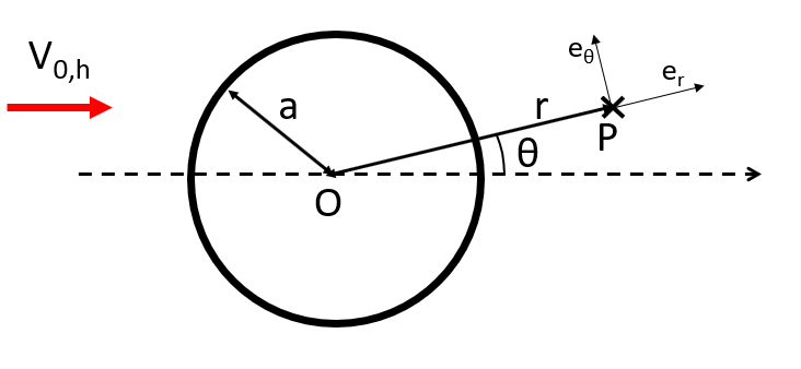
A tower shadow is not necessarily produced by a tubular tower. When using
truss towers, a tower shadow can be calculated based on a user-defined radius (see
shadow radius parameter in the
Aerodynamics tab).
The resulting wind velocity (i.e. the velocity of the wind affected by the tower) is noted
$$V$$
in the following figure, and is decomposed in the polar coordinate system into
$$V_{r}$$
and
$$V_{\theta}$$
.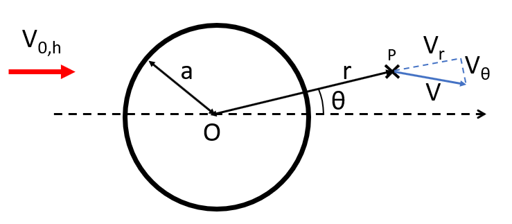
The components of
$$V$$
are then computed according to potential flow theory as
$$V_r = \left(1-\left(\frac{a}{r}\right)^2\right)|V_{0,h}|\cos{\theta}$$
for the component along
$$e_r$$
$$V_{\theta}= -\left(1+\left(\frac{a}{r}\right)^2\right)|V_{0,h}|\sin{\theta}$$
for the component along
$$e_\theta$$
$$|V_{0,h}|$$
is the magnitude of
$$V_{0,h}$$
.
Note: currently, Ashes only calculates tower shadows for vertical towers
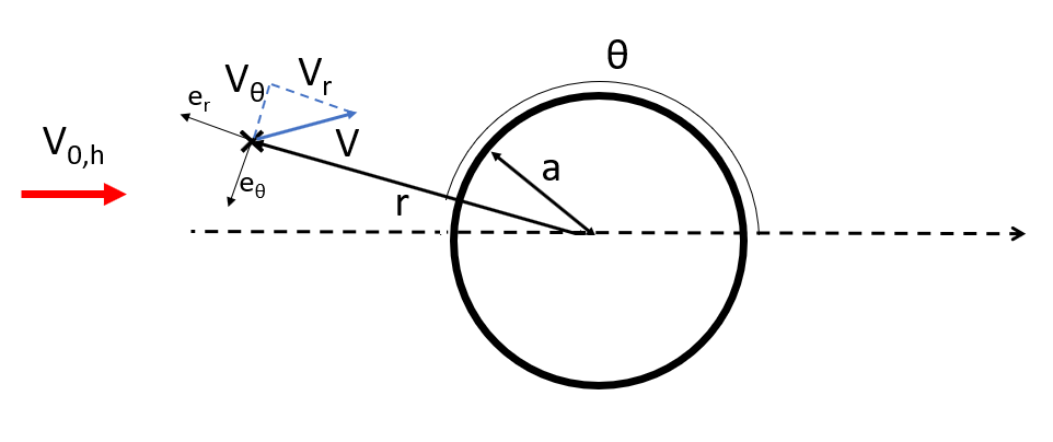
Note:
we have shown how to evaluate the wind
behind
the tower. For
upwind
turbines (which is the most common case in the industry), it is necessary to evaluate the wind
in front of
the tower. Obviously, the equations stay the same, but the
−
sign in the definition of
If this note makes things even more confusing, just ignore it. It will make sense if you try to write down the equations and start doubting about the definition of
$$V_\theta$$
can be confusing. This is due to the fact that in this case,
θ
will be larger than 90 degrees. The figure below illustrates the coordinates of point
P
when calculating the wind velocity in front of the tower.
If this note makes things even more confusing, just ignore it. It will make sense if you try to write down the equations and start doubting about the definition of
$$\theta$$
or the polar coordinate system.