Generator [Electrical] sensor
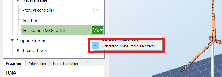
It is possible to add a sensor to the generator to obtain certain electrical output, by opening the Generator sensor dropdown menu and selecting
Generator [electrical], as shown in the image below. The algorithms/formulas used to calculate the output of this sensor is not yet documentd in the Theory manual. However, it is currently documented in a spreadsheet that is available to NTNU students.
This sensor only provides information for Generator of type
Permanent Magnet Synchronous Generators (PMSG). For other types of generators it will only output zeroes.
The
Generator [electrical] sensor provides the following fields:
| Field | Unit | Description |
| Voltage (induced) per phase (EMF) | V | EMF = Electromotive force. Cannot be measured directly. https://en.wikipedia.org/wiki/Electromotive_force |
| Voltage (terminal) per phase | V | The output voltage. Can be measured. The voltage is always smaller than the EMF because of internal losses (resistance). |
| Current per phase | A | The output current of the generator per phase. Can be measured. Proportional with the induced voltage (EMF). |
| Frequency | Hz | The frequency of the AC elecricity (voltage and current) that is produced by the generator. Proportional with the RPM and the number of poles. |
| Efficiency | - | Instantaneous efficiency of the electrical generator (output electrical power over input mechanical power) |
| Max power | W | Maximum electrical power that the generator can produce at the current operating point |
| Resistance for max power (and torque) | Ω | Load resistance that would give the maximum torque (and maximum power) for the current operating point |
| Stator coil reactance per phase | Ω | Resistance of one stator coil phase. Proportional to the stator coil inductance and electrical angular frequency |