Static pull: one-element model
1 Test description
This test uses a one element model to compute the displacement due to an external force. The model is associated to a cantilever beam, with one node clamped to the ground. A load is applied on the other node, and the displacement of that node is compared to the analytical solution.
By default, the element are
Euler-Bernoulli type elements.
For these tests, gravity and aerodynamic loads are disabled.
The following load cases are tested:
- Circular hollow cross section with a force in the x-direction
- Circular hollow cross section with a force in the y-direction
- Circular hollow cross section with a force at 45 degrees
- Circular hollow cross section with a force in the z-direction
- Circular hollow cross section with a moment around the z-direction
-
Circular hollow
cross section with a force in the x-direction, 20 m element
-
Circular hollow
cross section with a force in the z-direction, 20 m element
-
Circular hollow cross section with a moment around the z-direction, 20 m element
-
Circular hollow
cross section with a force in the x-direction, Timoshenko element
-
Rectangular hollow
cross section with a force in the x-direction
-
Rectangular hollow
cross section with a force in the y-direction
- Rectangular hollow cross section with a force in the x-direction 90 deg twist
-
Rectangular hollow cross section with a force in the x-direction 30 deg twist
- Circular shape cross section with a force in the x-direction
- Circular shape cross section with a force in the y-direction
- Circular shape cross section with a force in the z-direction
-
Circular shape
cross section with a moment around the z-direction
2 Analytical solution
2.1 Circular hollow cross section with a force in the x-direction
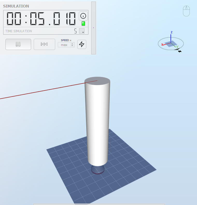
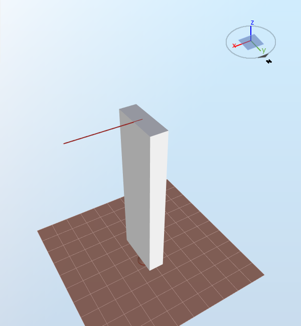
The model is shown in the figure below
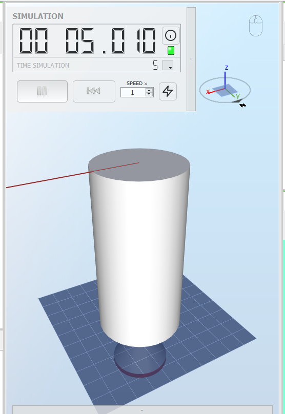
Note: circular hollow cross sections appear filled, but this only affects the visualization.
The circular hollow cross section has a radius
$$r = 1\text{ m}$$
and a thickness
$$t = 0.02\text{ m}$$
, which gives a second moment of inertia
$$I = \frac{\pi}{4}\left(r^4-(r-t)^4\right)=6.097\cdot10^{-2}\text{ m}^4$$
(see
https://en.wikipedia.org/wiki/List_of_second_moments_of_area).
The element has a length
$$l = 10\text{ m}$$
and the material has an Elastic modulus
$$E= 2.1\cdot10^{11}\text{ Pa}$$
. The point load applied to the top node in the x-direction is
$$P = 1\cdot10^6\text{ N}$$
.
According to the
Euler-Bernoulli beam theory (see
https://en.wikipedia.org/wiki/Euler%E2%80%93Bernoulli_beam_theory#Cantilever_beams), the
displacement
of the top node will be
$$d_x=\frac{P\cdot l^3}{3EI} = 0.0260\text{ m}$$
.
Given that the load is only applied in the x-direction, the displacement of the top node in the y-direction will be 0.
The
Shear force in the element will solely be due to the point load, therefore its value will be
$$F_x = 1\cdot10^6\text{ N}$$
. In this example, the x-direction corresponds to the first principal axis of the element (see the
Beam element sensor).
The
Bending moment at the bottom of the element (i.e. node i, see the
Beam element sensor) is simply
$$M = l\cdot P=10\text{ }000\text{ kNm}$$
. This will be around the second principal axis.
The
Maximum normal stress is given by
$$\sigma_n = M\cdot\frac{r}{I} = 164\text{ MPa}$$
(see
Stresses and responses)2.2 Circular hollow cross section with a force in the y-direction
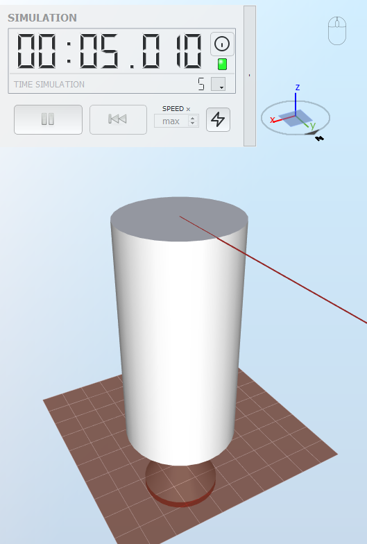
The model is shown in the figure below:
Following the derivation of the previous case, the top node displacement in the y-direction will be
$$d_y = 0.0260\text{ m}$$
and the displacement in the other directions will be 0.
Similarly, the
Shear force and the
Bending moment
will have the same values as in the previous case, but will be along the second principal axis and around the first principal axis, respectively.
The
Maximum normal stress will be the same as the previous case.
2.3 Circular hollow cross section with a force at 45 degrees
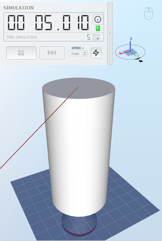
The model is shown in the figure below
In this test, we apply load
$$P$$
at a 45 degree angle from the x-direction. Therefore we apply a load in the x-direction
$$P_x = \frac{P\sqrt{2}}{2}$$
and a load in the y-direction
$$P_y = \frac{P\sqrt{2}}{2}$$
. Following the derivation of the previous sections, this will give displacements in the x- and y-direction of
$$d_x = 0.0184\text{ m}$$
and
$$d_y = 0.0184\text{ m}$$
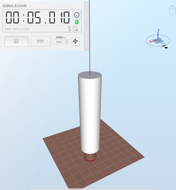
.2.4 Circular hollow cross section with a force in the z-direction
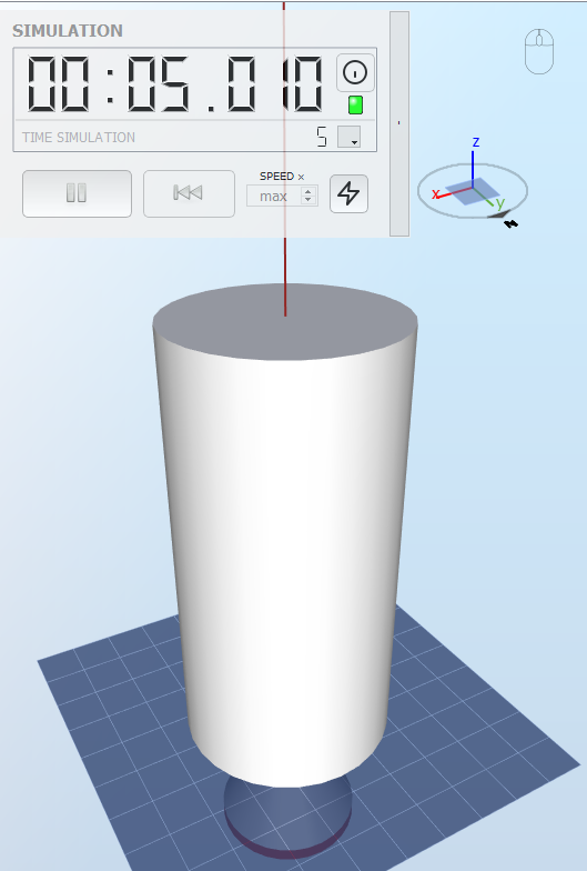
The model is shown in the figure below:
The circular hollow cross section has a radius
$$r = 1\text{ m}$$
and a thickness
$$t=0. 2\text{ m}$$
, which gives a structural area of
$$A = 0.124\text{ m}^2$$
.
With a load in the z-direction
$$P=1\cdot10^8\text{ N}$$
, the vertical displacement of the top node will be
$$d_z = \frac{Pl}{EA}=3.828\cdot10^{-2}\text{ m}$$
(see
https://en.wikipedia.org/wiki/Stiffness#Relationship_to_elasticity).
The reaction force of the element in the axial direction (also called
Axial force) will be equal to
$$P$$
since there is no gravity load.
The
maximum normal stress
will be
$$\sigma_a = \frac{P}{A} = 803.9\text{ MPa}$$
(see
Stresses and responses).2.5 Circular hollow cross section with a moment around the z-direction
The model is shown in the figure below:
In this test, we apply a moment
$$T= 1\text{ MNm}$$
on the top node of the model.
The moment of inertia around the z-axis for the cross section is
$$J = \frac{\pi}{2}\left(r^4-(r-t)^4\right)=0.1219\text{ m}^4$$
(see
https://en.wikipedia.org/wiki/List_of_second_moments_of_area).
The material has a poisson ratio
$$\nu = 0.3$$
and an elsatic modulus
$$E = 2.1\cdot10^{11}\text{ Pa}$$
, so its shear modulus is
$$G = \frac{E}{2(1+\nu)} = 80.77\text{ GPa}$$
The
Structural twist of the tope node, in degrees, is therefore
$$\theta_t = \frac{Tl}{GJ}\cdot\frac{360}{2\pi}=5.819\cdot10^{-2}\text{ degrees}$$
(see
Hibbeler (2013) eq 5-15). This is also equal to the
Rotational displacement around the z-axis.2.6 Circular hollow cross section with a force in the x-direction, 20 m element
The model is shown in the figure below:
The characteristics of the model are the same as in
Load case 1, but the length is now
$$l=20\text{ m}$$
.
Following the derivation of Load case 1, we find
$$d_x = 0.2082\text{ m}$$
$$M = 20000\text{ kNm}$$
$$\sigma_n = 328.0\text{ MPa}$$
2.7 Circular hollow cross section with a force in the z-direction, 20 m element
The model is shown in the figure below:
The characteristics of the model are the same as in
Load case 4, but the length is now
$$l = 20\text{ m}$$
.
Following the derivation of load case 4, we find
$$d_z = 76.80\text{ mm}$$
$$F_z = 100\text{ MN}$$
$$\sigma_a = 803.9\text{ MPa}$$
2.8 Circular hollow cross section with a moment around the z-direction, 20 m element
The model is shown in the figure below:
The characteristics are the same as in
Load case 5 but the length is now
$$l = 20\text{ m}$$
. Following the derication of load case 5, we find
$$\theta_t = 0.1163\text{ degrees}$$
2.9 Circular hollow cross section with a force in the x-direction - Timoshenko
The model is shown in the figure below>
The circular hollow cross section has a radius
$$r = 2.5\text{ m}$$
and a thickness
$$t=0.2\text{ m}$$
, which gives a second moment of inertia
$$I = \pi/4\left(r^4-(r-t)^4\right)=6.097\cdot10^{-2}\text{ m}^4$$
(see
https://en.wikipedia.org/wiki/List_of_second_moments_of_area) and a structural area
$$A = \pi r^2-\pi(r-t)^2$$
.
The element has a length
$$l=10\text{ m}$$
and the material has an Elastic modulus
$$E=2.10\cdot10^{11}\text{ Pa}$$
and a Poisson ratio
$$\nu = 0.3$$
, which gives a shear modulus
$$G=\frac{E}{2(1+\nu)}$$
The point load applied to the top node in the x-direction is
According to the Timoshenko beam theory (see https://en.wikipedia.org/wiki/Timoshenko-Ehrenfest_beam_theory), the displacement of the top node will be:
$$P = 1\cdot10^6\text{ N}$$
.
According to the Timoshenko beam theory (see https://en.wikipedia.org/wiki/Timoshenko-Ehrenfest_beam_theory), the displacement of the top node will be:
$$d_x = \frac{Pl^3}{3EI} + \frac{Pl}{\kappa AG}$$
where
$$\kappa$$
is the
Timoshenko shear coefficient. also called
shear correction factor.
In Ashes, for circular hollow cross-sections, we use
$$\kappa=0.5$$
.
This gives a displacement
$$d_x = 0.02802\text{ m}$$
2.10 Rectangular hollow cross section with a force in the x-direction
The model is shown in the figure below:
The rectangular cross section has a height
$$h = 3\text{ m}$$
(corresponding to the 1st axis) and a width
$$b=1\text{ m}$$
(corresponding to the second axis). In this configuration, the 1st axis is aligned with the x-axis. The thickness of the cross section is
$$t = 0.02\text{ m}$$
and the length of the element is
$$l = 10\text{ m}$$
. The Elastic modulus of the material is
$$E = 2.1\cdot 10^{11}\text{ Pa}$$
.
The point force applied to the top node in the x-direction is
$$P=1\cdot 10^6\text{ N}$$
.
The second moment of inertia for the 1st and 2nd axes are thus
$$I_x = \frac{hb^3-(h-2t)(b-2t)^3}{12}=3.178\cdot10^{-2}\text{ m}^4$$
$$I_y = \frac{bh^3-(b-2t)(h-2t)^3}{12}=1.753\cdot10^{-1}\text{ m}^4$$
The equation to determine the top displacement in the x-direction is the same as for
load case 1: Circular
hollow cross section with a force in the x-direction.
The second moment of inertia used in the equation must correspond to the axis
perpendicular to the load applied, thus we have
$$d_x=\frac{P\cdot l^3}{3EI_y}=9.057\cdot 10^{-3}\text{ m}$$
.
As for load case 1, we obtain a
Shear force
$$F=1\text{ MN}$$
and a
Bending moment
$$M = l\cdot P=10\text{ MNm}$$
The maximum normal stress is given by
$$\sigma_n = 0.5M\cdot\frac{h}{I_y} = 85.55\text{ MPa}$$
2.11 Rectangular hollow cross section with a force in the y-direction
The model is shown in the figure below:
The dimensions are the same as in the previous load case. Therefore, the displacement of the top node in the y-direction is now
$$d_y=\frac{P\cdot l^3}{3EI_x}=0.0500\text{ m}$$
The maximum normal stress is
$$\sigma_n = 0.5M\cdot\frac{b}{I_x}=157.5\text{ MPa}$$
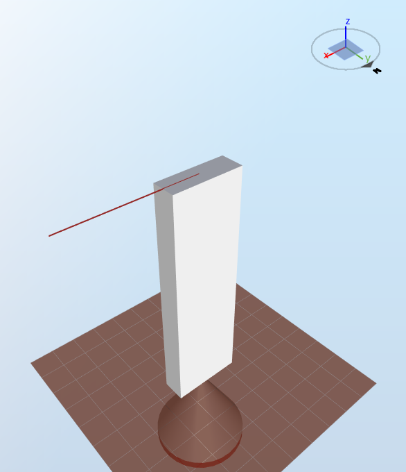
2.12 Rectangular hollow cross section with a force in the x-direction 90 deg twist
In this test, the model from the previous test has been rotated around the element axis by
$$\theta = -90\text{ degrees}$$
. The load is pulling in the x-direction.
The model is shown in the figure below:
This case is equivalent to load case 2.11 and serves only to check that the structural twist is applied correctly. We therefore expect the same results as load case 2.11
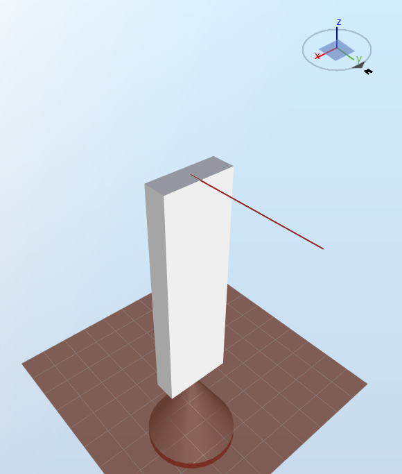
2.13 Rectangular hollow cross section with a force in the x-direction 30 deg twist
In this test, we use the rectangular model from load case 11 again, rotated by
$$\theta = -30\text{ degrees}$$
.
The model is shown in the figure below:
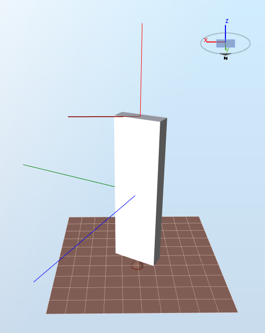
A force
$$\vec{F} = 1\text{ MN}$$
is applied on the top node in the x-direction.
In this configuration, the
first principal axis
corresponds to the green vector and the
second principal axis
corresponds to the blue vector. If we note
$$\vec{e_1}$$
and
$$\vec{e_2}$$
the unit vectors in the direction of the first and second principal axes, the force
$$\vec{F}$$
can be decomposed as
$$\vec{F}=F_1\cdot\vec{e_1}+F_2\cdot\vec{e_2}$$
, where
$$F_1 = \lvert\vec{F}\lvert\cos{\theta}=866\text{ kN}$$
and
$$F_2 = \lvert\vec{F}\lvert\sin{\theta}=500\text{ kN}$$
These forces will correspond to the shear forces at the bottom of the element. This also implies that the moments at the bottom of the elements areound the first and second principal axes will be, respectively
$$M_1 = F_2\cdot l$$
and
$$M_2 = F_1\cdot l$$
The displacement along the first principal axis
$$d_1$$
will be
$$d_1 = \frac{F_1l^3}{3EI_2}$$
$$I_2$$
is the second moment of inertia about the second principal axis. Using the formulae for
load case 12, we find
$$d_1=7.84\cdot 10^{-3}\text{ m}$$
.
Similarly, the displacement along the second principal axis will be
$$d_2 = \frac{F_2l^3}{3EI_1}=0.025\text{ m}$$
The total displacement
$$\vec{d}$$
is thus
$$\vec{d} = \vec{e_1}d_1+\vec{e_2}d_2$$
The unit vectors
$$\vec{e_1}$$
and
$$\vec{e_2}$$
can be written in terms of tunit vectors of the global coordinate system
$$\vec{e_x}$$
and
$$\vec{e_y}$$
as
$$\vec{e_1}=\cos{\theta}\vec{e_x}-\sin{\theta}\vec{e_y}$$
and
$$\vec{e_2}=\sin{\theta}\vec{e_x}+\cos{\theta}\vec{e_y}$$
By inserting this in the formula for the displacement, we obtain
$$\vec{d}=0.0193\vec{e_x} + 0.0177\vec{e_y}$$
The
maximum normal bending stress can be calculated using the formula in
Stresses and responses:
$$\sigma_n =0.5\left( \frac{\lvert M_1\lvert\cdot b}{I_1}+\frac{\lvert M_2\lvert\cdot h}{I_2} \right)= 153\text{ MPa}$$
2.14 Circular shape cross section with a force in the x-direction
The next four tests are similar to the test run with a circular hollow cross section, but using a
circular shape cross section instead. When using shape cross sections, the
structural properties
of the cross section, rather than the geometry, are given as an input.
The mode is shown in the figure below
The input to this cross section is the bending stiffness,
$$EI = 10\text{ GNm}^2$$
The element has a length
$$l = 10\text{ m}$$
and the point load applied to the top node in the x-direction is
$$P = 1\cdot10^6\text{ N}$$
.
According to the
Euler-Bernoulli beam theory (see
https://en.wikipedia.org/wiki/Euler%E2%80%93Bernoulli_beam_theory#Cantilever_beams), the
displacement
of the top node will be
$$d_x=\frac{P\cdot l^3}{3EI} = 0.0333\text{ m}$$
.
Given that the load is only applied in the x-direction, the displacement of the top node in the y-direction will be 0.
The
Shear force in the element will solely be due to the point load and will be in the opposite direction, therefore its value will be
$$F_x = -1\cdot10^6\text{ N}$$
. In this example, the x-direction corresponds to the first principal axis of the element (see the
Beam element sensor).
The
Bending moment at the bottom of the element (i.e. node i, see the
Beam element sensor) is simply
$$M = l\cdot P=10\text{ }000\text{ kNm}$$
. This will be around the second principal axis.2.15 Circular shape cross section with a force in the y-direction
The model is shown in the figure below:
Following the derivation of the previous case, the top node displacement in the y-direction will be
$$d_y = 0.0333\text{ m}$$
and the displacement in the other directions will be 0.
Similarly, the
Shear force and the
Bending moment
will have the same values as in the previous case, but will be along the second principal axis and around the first principal axis, respectively.
.
2.16 Circular hollow cross section with a force in the z-direction
The model is shown in the figure below:
The input to this model is the extensional stiffness
$$A = 25\text{ GN}$$
With a load in the z-direction
$$P=1\cdot10^8\text{ N}$$
, the vertical displacement of the top node will be
$$d_z = \frac{Pl}{EA}=0.040\text{ m}$$
(see
https://en.wikipedia.org/wiki/Stiffness#Relationship_to_elasticity).
The reaction force of the element in the axial direction (also called
Axial force) will be equal to
$$P$$
since there is no gravity load.2.17 Circular hollow cross section with a moment around the z-direction
The model is shown in the figure below:
In this test, we apply a moment
$$T= 1\text{ MNm}$$
on the top node of the model.
The input to this model is the torsional stiffness
$$GJ = 10\text{ GNm}^2$$
The
Structural twist of the tope node, in degrees, is therefore
$$\theta_t = \frac{Tl}{GJ}\cdot\frac{360}{2\pi}=0.0573\text{ degrees}$$
. This is also equal to the
Rotational displacement around the z-axis.3 Results
In Ashes, the loads are applied with a
ramp-up, i.e. they start at 0 and are progressively increased until their value (see
Analysis). Therefore, the output produced by Ashes will show a ramp-up period as well.
A passed test will therefore show a
red horizontal line
for the analytical results and a
blue smoothly increasing curve
for the results produced by Ashes, such as the one shown in the figure below:
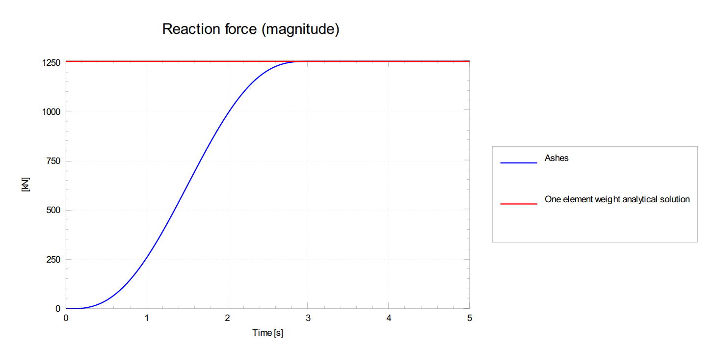
A test is considered passed when all values of the
last second of the results produced by Ashes are within 0.1% of the analytical solution.
The report for this test can be found on the following link: