DTU 10-MW
This document details how different parts of the DTU 10-MW reference wind turbine are implemented in Ashes.
1 Blade
The DTU 10-MW blade is based on the data published in this repository:
https://rwt.windenergy.dtu.dk/dtu10mw/dtu-10mw-rwt (last accessed February 2021). Five DTU blades are shipped with Ashes, named as follows:
- DTU 10-MW: the airfoils of this blade have 2D polars
- DTU 10-MW (no prebend): same as the previous one, but without out-of-plane prebending (see Blade shape file)
- DTU 10-MW 3D correction: the airfoils of this blade have been corrected to account for 3D effects (this blade includes prebending)
- DTU 10-MW adapted: same as the DTU 10-ME blade, but the polar of the FFA-W3-600 airfoil has been modified to solve the dynamic stall issue (see section 5 Dynamic stall issue at low speeds)
- DTU 10-MW 3D correction adapted: same as the DTU 10-MW 3D correction blade, but the polar of the FFA-W3-600 airfoil has been modified to solve the dynamic stall issue (see section 5 Dynamic stall issue at low speeds)
Note: the first of these blades is visible when opening the blade database. The last four are under the
Experimental blades sections, so you have to toggle that option to access them (see
Blade database)
1.1 Blade shape
For the
Blade shape file, we used the data provided in the
Excel spreadsheet, under the tab
Blade.
The section
Blade planform properties (Coarse N=40) provides the data necessary for the blade shape file in Ashes. Some modifications had to be made for some of the columns of the Ashes file, explained in the list below.
1.1.1 BlSpn
The
BlSpn column in Ashes is equal to the
z column in the Excel file minus the hub radius.
For a
Blade aerodynamical station
$$i$$
, the value for the BlSpn column will be
$$\text{BlSpn}(i) = \text{z}(i)-2.8$$
1.1.2 BlCrvAC
The BlCrvAC column in Ashes is the distance between the chordline midpoint and the pitch axis perpendicularly to the chordline. It is equal to the y column in the Excel file1.1.3 BlSwpAC
The BlSwpAC column in Ashes is the distance bwteen the chordline mispoint and the pitch axis along the chordline. It uses the Pitch axis aft LE (x/c) and the Chord colunms.
For a
Blade aerodynamical station
$$i$$
, the value for the BlSwpAC column will be
$$\text{BlSwp}(i)=\text{Chord}(i)/2-\text{Pitch axis aft LE (x/c)(i)}\cdot\text{Chord}(i)$$
1.1.4 BlCrvAng
No data is provided for
lCrvAng
1.1.5 TwistAngle
The
TwistAngle
column in Ashes is equal to the opposite of the
Twist Angle in the Excel file.
1.1.6 ChordLength
The
ChordLength column in Ashes is equal to the
Chord column in the Excel file.
1.1.7 AirfoilID
The
AirfoilID column in Ashs does not have an equivalent in the Excel file. The airfoil for each blade aerodynamical section was selected based on the AeroDyn input file provided in the repository, available in the folder
dtu-10mw-rwt/aeroelastic_models
fast/DTU10MWRWT_FAST_v1.00/ReferenceModal/10MWRWT.
Note:
the data from the FAST input files and from the Excel file do not have the same number of blade aerodynamical stations. It was therefore necessary to interpolate between the two.
1.2 Blade structure
For the
Blade structure file, we use the Hawc2 input file provided in
this link. This file corresponds to the fully flexible blade with torsion. The equivalence between the Ashes input and the Hawc2 input is given in the
Hawc2 to Ashes document.
Note: the file in the link contains two sets of data. The second set of data models a stiff blade, as can be seen from the unphysically large Elastic and Shear modulus.
2 Airfoil data
The data for the
Airfoil polar file are taken from the aforementionned Excel file, from the
Airfoildata table.
Note: two sets of polars are gien in the specification document: one for 2D polars and one with a 3D correction applied. Two blades are provided with Ashes, using both polar sets.
The data for the
Airfoil geometry file for the airfoils FFA-W3-360, FFA-W3-301 and FFA-W3-241 are taken from
Bjørk (1990).
The data for the
Airfoil geometry file for the airfoils FFA-W3-480 and FFA-W3-600 are taken from the folder
dtu-10mw-rwt/CFD/2D. Note that the number of geometry points in Ashes has been reduced.
3 Controller
The source code for the DLL controller for the DTU 10-MW wind turbine has been downloaded from the repository
https://gitlab.windenergy.dtu.dk/OpenLAC/BasicDTUController.
Some modifications to the code were made, which can be found in the Ashes folder, generally
Documents/AshesX.xx/DLL controllers/BasicDTUController/src/Modifications done for use in Ashes.txt
The input file
controller_input.dat was modified so that the model in Ashes matches the simulations from the specification document (see
DTU 10-MW steady state performance).
A controller named
BasicDTUController_StiffStructure was created to match the stiff model simulations from the specification document (see
DTU 10-MW steady state performance, stiff blades). Only the values in the
wpdata.100 document are different for the stiff model compared to the flexible one.
4 Dynamic stall issue at low wind speeds
While trying to verify our model against the DTU 10-MW specification document (see
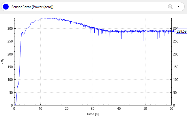
DTU 10-MW steady state performance), we noticed an unexpected behaviour at low wind speeds: The
Aerodynamic power (from the
Rotor [Aero] sensor) exhibits very strong oscillations around 280 kW (which is the expected value from the specification document). This is illustrated in the graph below:
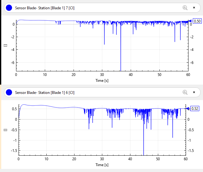
Upon investigation accross the blade span, it appears some of the blade stations in the inner part of the blade also show these strong oscillations in their lift coefficient time series. The graphs below show the lift coefficients for blade stations 6 and 7 on blade 1 (located 14 and 17.1 m from the blade root, respectively).
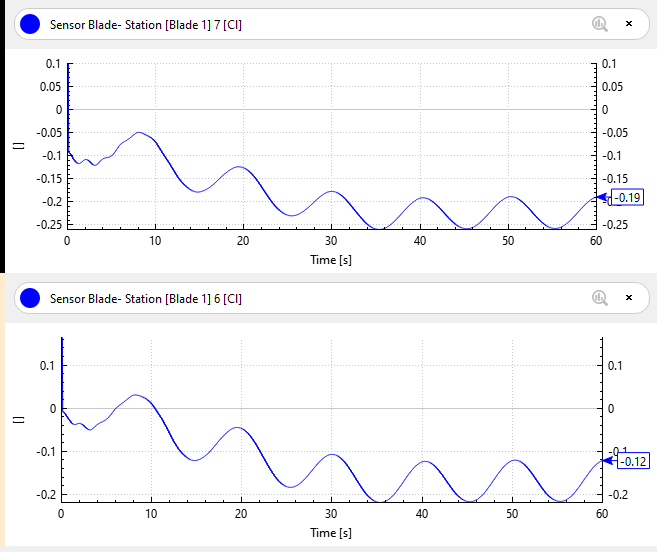
This appears to be due to the dynamic stall correction (see
Unsteady BEM). Indeed, the same simulation with the dynamic stall correction disabled yields the following results:
The reason for this unexpected behaviour of the dynamic stall correction is the presence of a 'kink' in the lift coefficient vs angle of attack curve, plotted below:
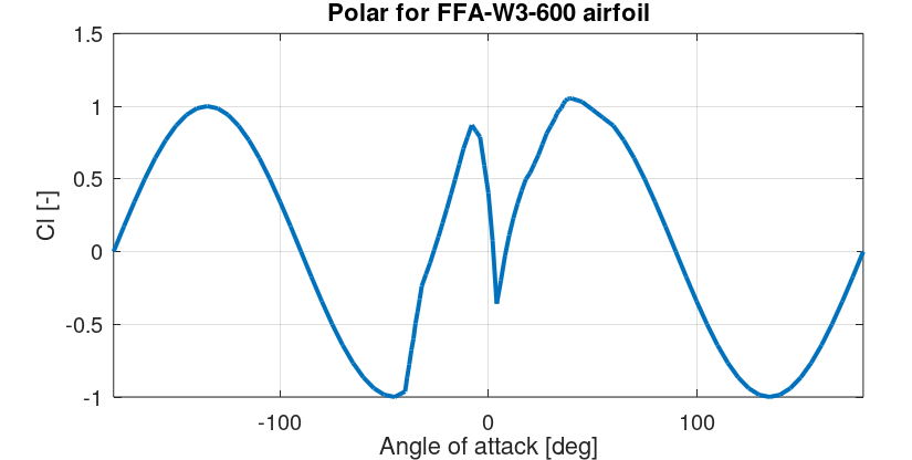
This polar comes from the specification document, where a note is made about the unusual polar shape: "The kinks in the curve at low AOA's for 48 and 60% airfoils are from the 2D CFD and is kept because this probably also will be seen in wind tunnels."
The implementation of the dynamic stall model in Ashes assumes that the lift coefficient curve is monotonically increasing from roughly -20 degrees up to the stall region. Using the polar shown in the figure above poses problems as dynamic stall corrections are applied even though the angle of attack is not in the stall region.
Since we currently have no dynamic stall model that can deal with such a polar, the current recommendation is to use the
Steady BEM for this cases. Note that it is not currently possible for users to disable the dynamic stall correction and still use the
Unsteady BEM.
Another possibility is to generate a different polar for the airfoil, for example using XFoil. It is expected that this will not have large effects on the overall results as the blade sections using the FFA-W3-600 airfoil are very close to the root. We ship two DTU blades that use a different polar for the FFA-W3-600 airfoil, namely the
DTU 10-MW adapted and the
DTU 10-MW 3D correction adapted blades.