Linear analysis
Ashes offers the possibility to run simulations using a
linear
or a
non-linear
algorithm. This can be changed in the
Analysis tab of the
Analysis parameters dialog.
When a linear simulation is carried out, the external forces (also called excitation forces, such as aerodynamic or hydrodynamic loads) are calculated on the initial position of the system: the deflections that occur during the simulation will not be taken into account when computing the forces. In addition, the mass, damping and stiffness properties of the system are time-independent, so they are based on the initial position of the structure. This is typically accurate enough when the structure experiences small deflections. Consider the following examples:
- A floating wind turbine will drift over time and move away from its initial position. If a linear analysis was carried out on a floating wind turbine, the wave loads would be computed as if the floater was still at its initial position, which will produce inaccurate wave loads. In that case, a non-linear analysis is required.
- A bottom-fixed wind turbine with a parked rotor will experience small deflections, and will therefore remain close to its initial position. In such a situation, it a linear analysis typically gives results similar to a nonlinear analysis.
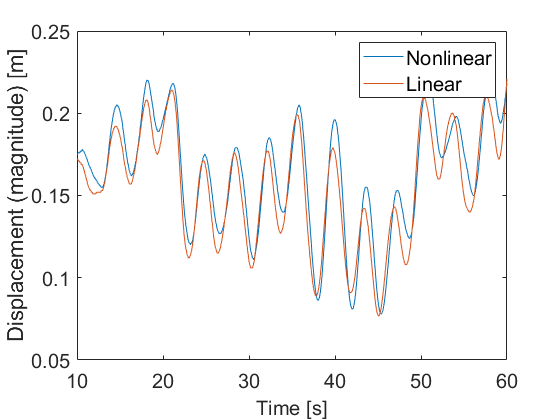
In the following paragraph, we compare simulation results for a linear and a non-linear analysis for a bottom-fixed wind turbine with locked main shaft under turbulent wind (with an average wind speed of 20 m.s
-1) and irregular seas (with H
S
= 6 m and T
P
= 10 s). Figures 1 and 2 show the bending moment at the lowest element of the monopile and the displacement at the top of the tower, respectively, for a simulation carried out with the nonlinear and the linear algorithm. For both output, the extreme values of the linear solution lie within 10% of the non-linear solution. Note that these conditions do not corrrespond to a realistic situation, as a locked rotor will generally have its blades pitched and therefore reduce the thrust load.

Note: in Ashes, it is not possible to run linear solution on
floating wind turbines as those models experience large displacements from their initial position and that could lead to inaccurate results. For bottom-fixed wind turbines with rotating rotors, it is not recommended to run linear analysis for the same reason. A linear analysis can be carried out on bottom-fixed turbines whose main shaft is locked (see
Main shaft)
1 Small deflection elements
It is possible to set the elements of the support structure as
Small deflection elements in the
Advanced tab of the
Analysis section in the
Analysis parameters. If this option is not selected, the elements are
co-rotational elements.
This is generally recommended for onshore and bottom-fixed offshore models since
- the displacements experienced by the support structure are small
- Rayleigh damping can be applied to small deflection elements
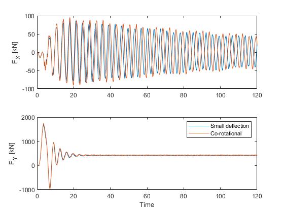
Another effect is that the effective natural periods of the model will be slightly shorter than with co-rotational elements. The image below shows the shear forces at the bottom of the tubular tower for the default offshore template, with no waves and a wind speed of 19 m.s
-1. While there is no significant difference in the shear force in the wind direction (see bottom plot), the side-to-side eigenperiod is about 2% shorter with the small deflection elements.