Blade shape file
To compute the aerodynamic loads on the turbine, ashes uses the
BEM algorithm. This requires that the blade is defined at a number of
Blade aerodynamical station
s which have their own aerodynamic properties. The
Blade aerodynamical station has an influence on the blade over a length called
Influence length.
The
Blade shape file is divided into three sections:
Airfoils,
Blade length and
Aerodynamical stations.
1 Airfoils
The
Airfoils section defines which airfoils are needed to define the blade. Each airfoil is determined by a
Nickname, which is used to refer to the respective airfoil within the Blade shape file, and a
Name in airfoil database, which is the name that the airfoil has in th
Airfoil database.
If the
Name in airfoil database
does not correspond to an existing airfoil, you will be prompted with an error message. This means that when creating a blade that requires new airfoils, you will first need to create the airfoils in Ashes, and then import the blade.
2 Blade length
Here you need to specify the length of the blade. This corresponds to the length of the projection of the blade onto the pitch axis at the beginning of the simulation, as explained in the
Blade length document.
3 Aerodynamical stations
This section specifies the characteristics of each
Blade aerodynamical station. Each station is defined by the following parameters:
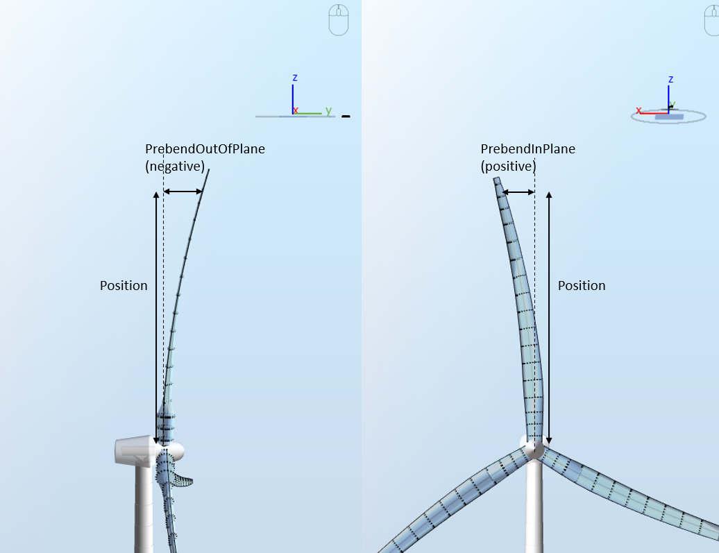
| Position | (m) | Blade span: distance from the blade root to the projection of the current blade station onto the Pitch axis. |
| PrebendOutOfPlane | (m) | The local out-of-plane offset of the Chordline midpoint with respect to the Pitch axis. |
| PrebendInPlane | (m) | The local in-plane offset of the Chordline midpoint with respect to the Pitch axis. |
| Curvature angle | (deg) | The local angle from the blade-pitch axis of a vector normal to the plane of the airfoil (currently not in use) |
| Twist angle | (deg) | Twist angle at the respective Blade aerodynamical station |
| Chord length | (m) | Chord length at the respective Blade aerodynamical station |
| Airfoil nickname |
(-)
|
Airfoil ID, indicates which airfoil is used at the respective Blade aerodynamical station. The airfoils are listed in the 'Airfoil Information' section further up in the file and this number must refer to the index of the requested airfoil in that list. |
Table 1
Ashes blade definition parameters
Note: previous versions of Ashes included the parameters
BlRelThick (blade relative thickness) and
BlPAD (blade pitch axis distance). These were only used for visualization purposes and have now been removed from Ashes.
The figures below illustrate the
Position, the
PrebendOutOfPlane
and the
PrebendInPlane
parameters. The left figure corresponds to a blade with negative PrebendOutOfPlane values and the right figure corresponds to a blade with positive PrebendInPlane values.
The image below corresponds to the blade shape file for the NREL 5 MW blade. This file can be obtained by exporting the blade shape file from the
Blade database. It will be used here as an example of the format used by Ashes. Note that the first column (in grey) is only indicating the line number and is not part of the actual text file.
Note: the position of the last
Blade aerodynamical station must correspond to the blade length, otherwise you will be prompted with an error message.