Note that the forces displayed in the velocity triangle are projected on the airfoil plane, which means that they don't necessarily match the 3D forces. For example, on a turbine with a 2.5 degrees cone angle and 0 tilt (and neglecting the blade deflection), the thrust force shown in the velocity triangle (i.e. the projected thrust force) will be cos(2.5) times smaller than the 3D thrust force acting on the element.
Due to the small cone and tilt angle and blade deflection, the difference is generally not sognificant. However, in order to avoid this inaccuracy, the cone and tilt angle can be set to 0, and the blades have to be stiff.
Velocity triangle
Ashes offers the possibility to open the velocity triangle at a given blade station. This enables to visualize the different velocities affecting the element and the aerodynamic loads thus induced. A video explainig the velocity triangle can be found here:
https://www.youtube.com/watch?v=OOP6Mbn0Gbw
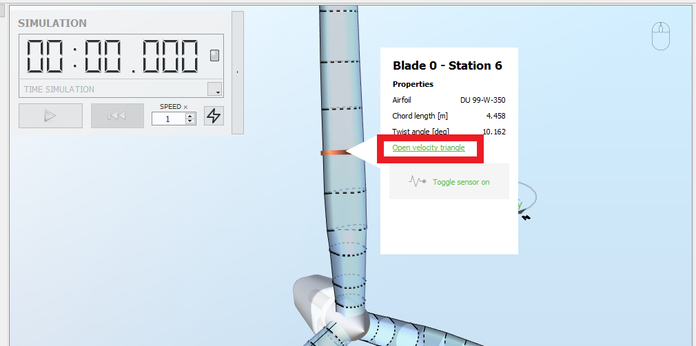
To open the velocity triangle, right-click on the desired blade station and click the
Open velocity triangle link, as shown in the picture.
When the velocity triangle is opened, the following pop-up window appears.
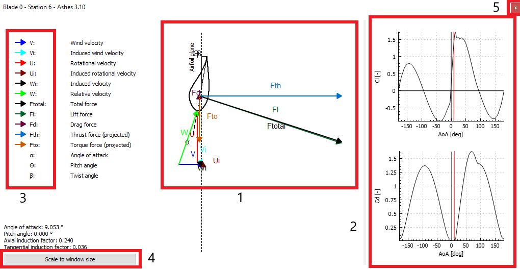
The following parts can be seen in the pop-up window
- Main window: this area displays the airfoil at this blade station and the different vectors and angles computed by the BEM code (see the Aerodynamic loads section of the theory manual). These parameters will change overtime depending on the environmental conditions. For example, if the blade starts pitching, the airfoil will start rotating accordingly.
- Polars pane: these graphs show the lift coefficient (Cl) and the drag coefficient (Cd) curves over the angle of attack. The vertical red line indicates the current angle of attack and enables to see the corresponding lift and drag coefficients. It is possibble to shange the size of this pane by dragging the separation between the pane and the main window sidewise
- Vectors: the list of the vectors used in the velocity triangle is given here. It is possible to toggle on and off the visualization of each vector by click on the arrow left to the name of the vector in this list.
- Scale to window size: this button enables to scale the velocity triangle to the available size. This can be useful when resizing the polars pane or when zooming the triangle.
- Close button: press this button and your freezer will instantly be filled with chocolate ice cream! Just kidding, this just closes the window.