Airfoil geometry file
Airfoils in Ashes can have a
geometry, which can used
-
for visualization purposes
- for analyzing the aerodynamic properties of the airfoil (see Airfoil database)
Aerodynamic loads obtained from the
BEM algorithm
during the simulation are not calculated from the geometry but from an
Airfoil polar file, it is therefore not necessary for airoils to have a geometry file (however, all airfoils used in a time simulation must have an
Airfoil polar file).
By definition in Ashes, the airfoil geometry is normalized against the chordlength and will therefore not contain any reference to an absolute length. When a blade is defined, the chordlength of each blade station will be used to compute the absolute geometry of the airfoil (see Blade shape file).
By definition in Ashes, the airfoil geometry is normalized against the chordlength and will therefore not contain any reference to an absolute length. When a blade is defined, the chordlength of each blade station will be used to compute the absolute geometry of the airfoil (see Blade shape file).
Note: if an airfoil does not have a geometry defined, it will be visualized with the geometry of the
NACA 64-618 airfoil.
The geometry file is composed of three sections:
- The first section indicates the number of coordinates used to define the geometry of the airfoil. This section has only one number, and is not used by Ashes in any way
-
The second section contains the coordinates of the
Aerodynamical reference point.
Note: currently, only the x coordinate is considered in Ashes. This means that the reference point can only be placed along the chordline -
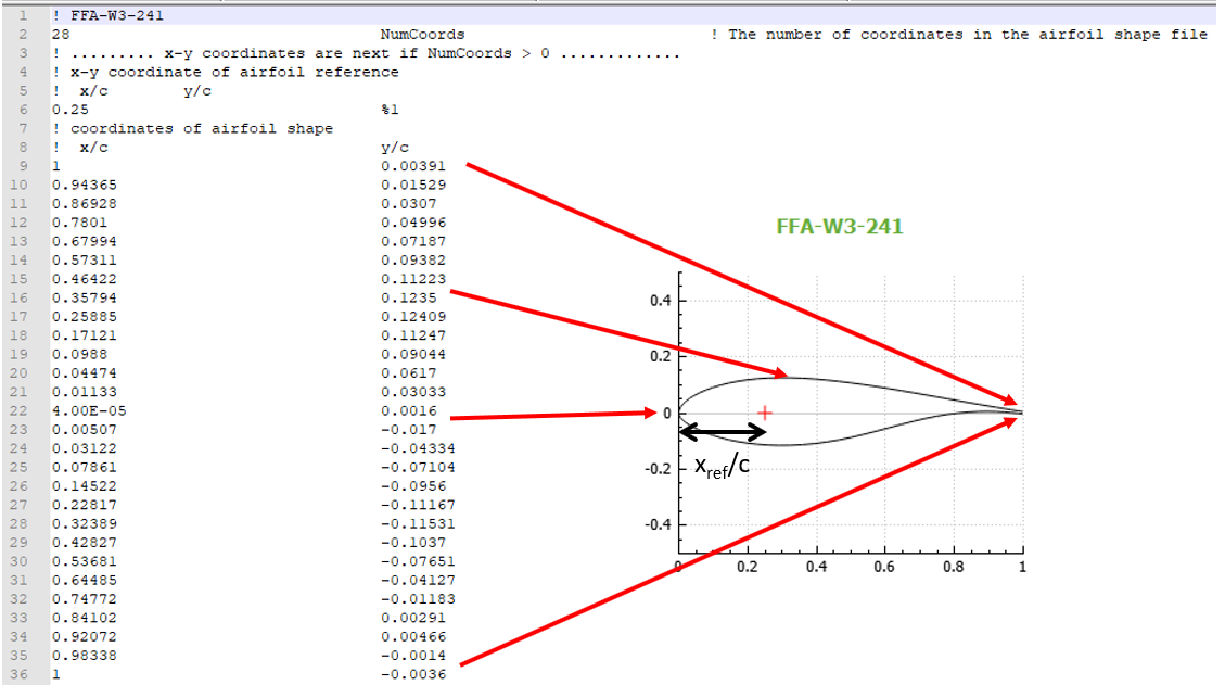
The third section contains the coordinates of the geometry of the airfoil and is composed of two columns
- The first column contains the x-coordinate (i.e. the position along the chordline) normalized against chordlength, where 0 corresponds to the leading edge and 1 corresponds to the trailing edge
- The second column contains the y-coordinates normalizewd against the chordlength, where negative values correspond to the pressure side and positive values correspond to the suction side
The first pair of coordinates correspond to the trailing edge on the suction side, the next ones correspond to a point moving from the trailing edge to the leading edge following the suction side and then back to the trailing edge following the pressure side.
The image below shows how the coordinates given in the text file correspond to the arifoil geometry. In this figure, the coordinate of the
Aerodynamical reference point is noted
x
ref.Note that the first column (in grey) is only indicating the line number and is not part of the actual file.
An example of the format can be obtained by exporting the geometry file from an existing airfoil in Ashes.
Note: the geometry of the DU airfoils cannot be exported since they have not been made available publicly.
More information
about airfoils is given in the following video:
https://www.youtube.com/watch?v=xZL7A55aE-0