Pitch axis
The pitch axis is the axis around which a blade pitches during operation (see
Pitch). It is a characteristic of the blade itself, there are therefore as many pitch axes as blades in a turbine. The figure below shows a turbine where all three blades have a
0 degrees pitch angle (left picture) and a
90 degrees pitch angle
(right picture)
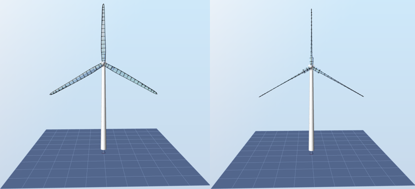
From the left figure to the right figure, the blades have rotated around the
pitch axis.
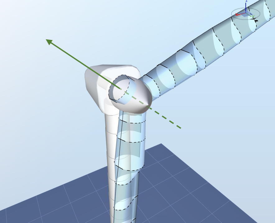
The most intuitive definition of a blade's pitch axis is the axis that is
perpendicular to the innermost blade aerodynamical station
(i.e. at the blade root) and that goes
through the centroid of the innermost blade aerodynamical station. As the innermost blade station is often a circle, the centroid corresponds to the center of the circle. The figure below illustrates the pitch axis for a blade for which only the first element is shown.
However, it is in theory possible that the previous definition does not apply since
- if a pre-bending is applied to the blade, it can be that the blade aerodynamical station is not perpendicular to the pitch axis
- the blade aerodynuamical station can be positionned such that the pitch axis does not go through its center
The following steps provide a thorough definition of the pitch axis for the first blade in Ashes (i.e. the blade pointing upwards when opening a template model).
1) Define the
rotor plane. The rotor plane is perpendicular to the main shaft and contains the hub.

The rotor plane is
not
perpendicular to the ground in general since the main shaft can be tilted with respect to the horizontal plane.
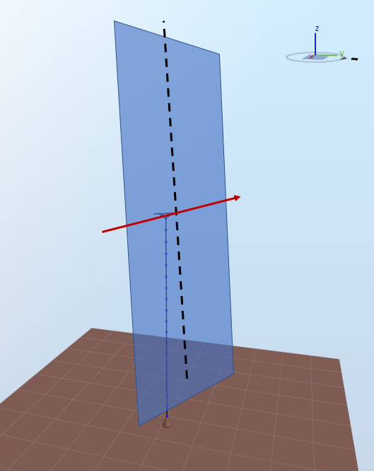
2) Take the horizontal axis in the rotor plane that goes through the hub, marked in red in the figure below.
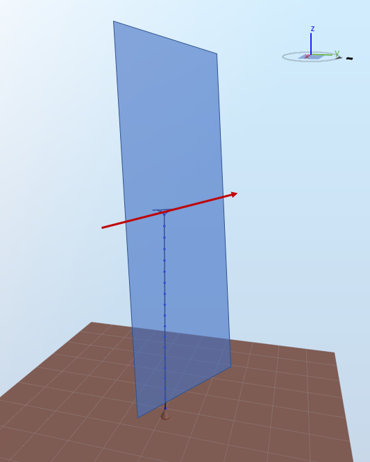
3) Take the projection of the
vertical axis (defined by the gravity, noted
z in the image below) going through the hub onto the rotor plane. This projected axis is represented with a black dotted line in the figure below.
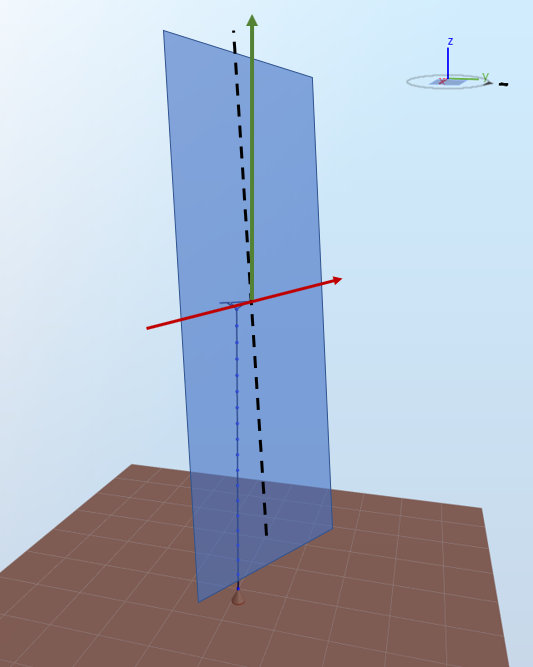
4) Rotate the projected vertical axis around the red horizontal axis by the
cone angle. The axis thus obtained is the
pitch axis for the first blade, shown in green in the figure below.
5) For turbines with
$$N$$
blades where
$$N>1$$
, the pitch axis of blade number
$$n$$
is obtained by rotating the pitch axis of blade number 1 around the main shaft axis by
$$\frac{n-1}{N}*360$$
degrees
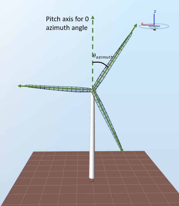
Note:
the pitch axis follows the blade. If the azimuth angle is not zero (because the blades are rotating or because of a non-zero initial azimuth angle), the pitch axes defined as above wil be rotated around the main shaft axis by the azimuth angle