- The HHT method as implemented in Ashes was derived by Hilber et al. (1977) and is explained in Crisfield et al. (1997). In the latter, this method is also named alpha-method after the parameter used to tune it
- The generalized-alpha method was derived by Chung et al. (1993). This is not the method implemented in Ashes
Damping
1 Numerical damping
During a time simulation, high frequency reponses may occur that do not have any physical meaning but that are rather an artifact of the numerical algorithm. These can be removed by applying numerical damping to the equations.
In Ashes, we have implemented the
Hilbert-Hughes-Taylor (HHT) method to have the possibility to add numerical damping. In effect, the HHT method is a modification of the
Newmark-beta method (used in Ashes to solve for the equation of motion). The HHT method implemented in Ashes follows the derivation of
Crisfield et al. (1997). The alpha parameter discussed in their paper can be modified in the
Advanced section of the
Analysis tab, under the
HHT-alpha parameter.
By default, a value of -0.025 is suggested. This value effectively dampens out most of the high frequencies while not affecting significantly the lower frequencies (this frequencies are generally dampened out by using Rayleigh damping). Note that a value of 0 will not produce any numerical damping, and the method reduces to the Newmark-beta method.
Note: there seem to be some confusion in the literature about the naming of this method:
2 Rayleigh damping
Rayleigh damping is implemented following the classical equation
$$C=\mu M + \lambda K$$
where
-
$$C, M, K$$are the damping, mass and stiffness matrices, respectively
-
$$\mu$$is the mass proportional damping coefficient
-
$$\lambda$$is the stiffness proportional damping coefficient
The
$$\lambda$$
and
$$\mu$$
coefficients can be set in the
Damping
section of the
Analysis tab in the
Analysis parameters window.
Note: rotational inertia has not been implemented for elements, which means that the mass matrix for rotational degrees of freedom is 0. This implies that Material damping does not apply to rotational motions of an element.
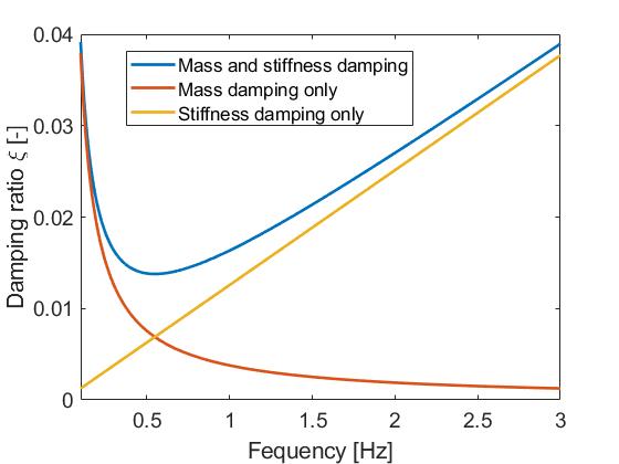
This produces a damping ratio that varies with the frequency of the response following the equation
$$\xi=0.5\left(\frac{\mu}{2\pi f}+\lambda 2\pi f\right)$$
$$\xi$$
is the damping ratio and
$$f$$
is the frequency of the response. It is common to refer to the first and second terms of the equation as the
Mass
and the
Stiffness
terms, respectively. As shown in the equation, the mass terms produces a damping ratio inversely proportional to the frequency whereas the stiffness term produces a damping ratio proportional to the response. This is illustrated in the figure below, where
$$\mu=0.47$$
and
$$\lambda = 0.04$$
have been chosen.
Note: under certain circumstances, it can be desirable to use only stiffness proportional damping, since the mass term will give damping due to rigid body motions. This can be the case for floaters or rotating blades, both of which undergo rigid body motions. In these cases, it is recommended to use only the stiffness term of Rayleigh damping.
It should also be noted that Rayleigh damping does not offer the possibility to tune the damping for any number of frequencies. The recommended practice is to tune the damping ratio for two modes of the structure, as explained in
How to use Rayleigh damping.
3 Aerodynamic damping
An important contribution for the damping of the first mode of a typical bottom fixed offshore turbine comes from the aerodynamic forces on the rotor (see for example
Hansen (2008d)). This can be understood as follows: if a turbine is oscillating in its fore-aft mode, its rotor will alternate between moving into the wind and moving away from the wind. When it is moving into the wind, the relative velocity of the wind will be equal to the incoming wind velocity plus the motion of the rotor. This will produce a higher relative velocity than if the turbine was still which will produce a larger thrust and will tend to reduce the motion of the turbine. Similarly, when the turbine is moving away from the wind, the thurst force will be lower than in a still position, which will produce the same effect.
Aerodynamic damping is a consequence of aerodynamic loading, and as such is inherently included in Ashes.
Note:
- Negative aerodynamic damping can occur and is especially relevant for floating wind turbines if no precautions are taken with the control strategy (see for example Nielsen et al. (2008b)). Jonkman (2010l) presents a controller for floating wind turbines specifically designed to avoid this issue, which is provided as a dll in Ashes in the folder Controller/OC3 PhaseIV
- Aerodynamic damping is greatly reduced when the turbine is parked or idling since the blades are pitched to reduce the thrust on the rotor (see Shirzadeh et al. (2015))
4 Hydrodynamic damping
For offshore wind turbines, another important source of damping comes from the hydrodynamic drag on the wetted element. Similarly to aerodynamic damping, hydrodynamic drag forces will produce a force that opposes the motion of the structure, therefore dampening out that motion.
This effect is inherently included in Ashes.
Note:
radiation damping is taken into account for cylindrical elements through the inclusion of the MacCamy-Fuchs theory (see
MacCamy et al. (1954))
5 Other sources of damping
Other sources of damping such as soil damping (dissipation of kinetics energy through heat due to friction in the soil) or damping devices (such as tuned mass dampers) can be added by adding damping loads on the support structure in the text input file (see
Keywords - damping loads).
6 Relative contribution of sources of damping
In this section, we compare the importance of different sources of damping by performing a decay test on the default offshore template. For this, we lock the main bearing and we apply a load of 1 MN on the node at the top of the tower. The wind speed is 11.4 m.s
-1. After the transients have died out, the load is released and the time series of the displacement of this node is analyzed.
Note: because the load is applied at the highest node of the tower, most of the response of the structure occurs in its first mode. Therefore, all damping ratios given in this section refer to the first mode, even though some higher mode response is present.
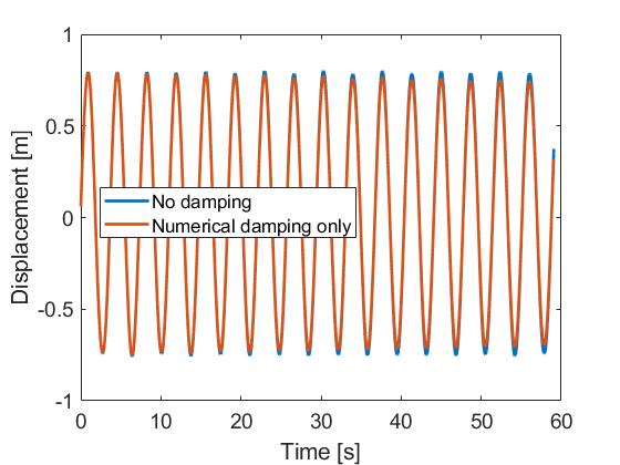
The figure below shows the decay of the displacement for a case with no damping at all (i.e. no numerical damping, no Rayleigh damping, aerodynamic and hydrodynamic loads turned off). As can be seen from the graphs, adding numerical damping only slighty increases the damping, giving a damping ratio lower than 0.1%. This is expected, since, as mentionned previously, numerical damping affects mostly high frequencies.
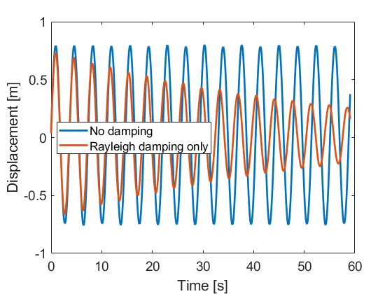
The following figure shows the decay test performed for the
No damping case and a case with Rayleigh Stiffness proportional only damping. For the latter, the stiffness damping coefficient is set so that the damping ratio at the first natural period of the system, i.e. 3.67 s, is 1%.
This figure shows how damping slightly decreases the eigenperiod of the system. This can be found for example in
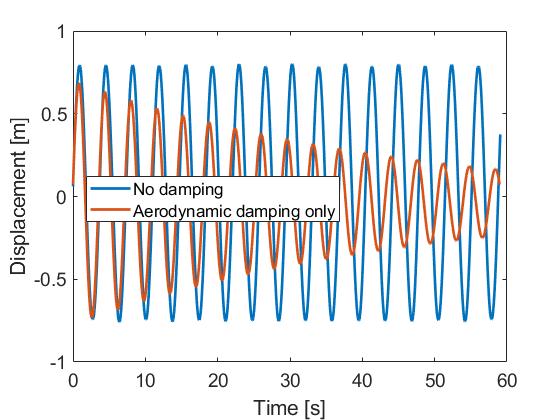
The following figure shows the influence of aerodynamic damping under the aforementioned conditions (i.e. locked rotor and wind speed of 11.4 m.s
-1). For this test, the aerodynamic loads are turned on.
This figure shows the importance of aerodynamic damping, which here produces a damping ratio at the first eigenperiod of about 1.2%.
Note:
for the case with wind loads, the displacement tends to a non-zero value. This residual displacement is due to the aerodynamic thrust on the rotor.
The aerodynamic damping is
very
dependent on the wind speed and on the operational conditions of the turbine. In the following figure, we compare the aerodynamic damping for a locked rotor for three different situations:
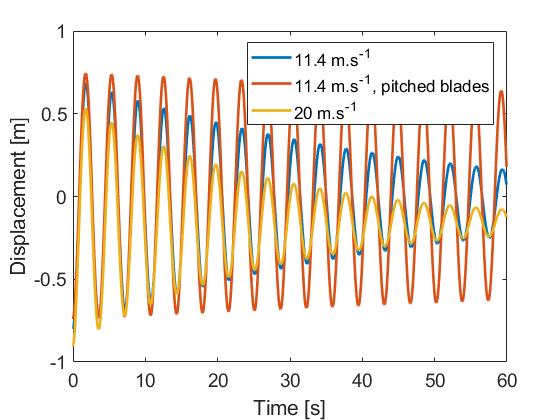
- a wind speed of 11.4 m.s -1
- a wind speed of 11.4 m.s -1, but with the blades pitched to feather (typically used to reduce the aerodynamic loads in storm conditions)
- a wind speed of 20 m.s-1
This figure shows that the a
erodynamic damping is significantly reduced when the blades are pitched (here the damping ratio is about 0.15% for the first mode). This is expected, since the reason for pitching the blades is to reduce the influence aerodynamic load.
It can also be seen that the aerodynamic damping is larger at higher wind speeds (in this case, 2.1% at 20 m.s
-1
vs 1.2% at 11.4 m.s
-1)
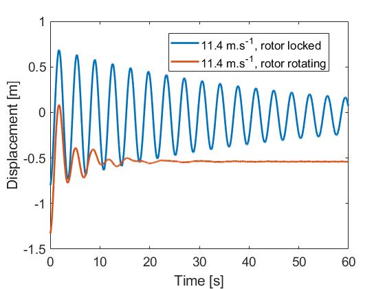
The last figure compares the situation where the rotor is locked and the normal operational conditions, which at 11.4 m.s
-1
correspond to the rotor rotating at about 12.1 RPM.
In the case of a rotating rotor, the aerodynamic damping is much larger than for all other cases. However, it is not straighforward to estimate the damping ratio, since a many modes of the structure come into play. An average of the logarithmic decrement over the first 3 oscillations gives a damping ratio of 17% for the first mode. The following table sum up the findings of this section:
| Damping case | Numerical | Rayleigh | Aero at 11.4 m.s-1 | Aero at 11.4 m.s-1 with pitched blades | Aero at 20 m.s-1 | Aero with rotating rotor |
| Damping ratio | < 0.1% | 1% | 1.2% | 0.15% | 2.1% |
17%
|
This section shows that in operational conditions, aerodynamic damping is largely dominant over other sources of damping. However, when the turbine is parked or idling (i..e with its blades pitched to feather to reduce the aerodynamic loads), the aerodynamic damping is drastically reduced, in which case it is important to have Rayleigh damping.