Cylindrical blade
1 Test description
This test uses a blade which only has cylindrical airfoils. The blade is fixed onto the hub and therefore does not rotate. The analysis is run in
Dynamic
and
Loads only modes, but the blade is stiff enough so that its deformation will not have significant effects on the results. The wind is constant and uniform
The following load cases are tested.
- 10 ms
- 5 ms
- 10 ms 90 deg
- 10 ms tilt 5 deg
- 10 ms cone 2.5 deg
2 Model
The model used for this test is shown in the figure below
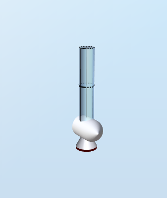
The airfoil used for this blade is the
Cylinder 1 airfoil used for the NREL 5-MW reference blade. It has constant lift and drag coefficients
$$C_L = 0$$
and
$$C_D=0.5$$
across the full 360 degrees span. The chord length is constant across the blade span and equal to
$$D=1\text{ m}$$
.
The blade has a length
$$L=5\text{ m}$$
and is composed of 2 elements. This implies that there are three
Blade aerodynamical station:
Blade station1
at the root,
Blade station 2
2.5 meters away from the root (at half-span) and
Blade station 3
at the tip. The root and tip blade aerodynamical stations have an
Influence length
$$L_{I1} = L_{I3} = 1.25\text{ m}$$
1.25 m, the one at half-span as an influence length
$$L_{II2} = 2.5\text{ m}$$
. The table below gives a summary of the relevant blade characteristics:| Blade aerodynamical station | Distance to blade root | Influence length |
| 1 |
$$r_1 = 0$$
|
$$L_{I1}=1.25\text{ m}$$
|
| 2 |
$$r_2 = 2.5\text{ m}$$
|
$$L_{I2} = 2.5\text{ m}$$
|
| 3 |
$$r_3 = 5\text{ m}$$
|
$$L_{I3} = 1.25\text{ m}$$
|
The air density is
$$\rho = 1.225\text{ kg}\cdot{m}^{-3}$$
, gravity forces have been turned off and tip and hub loss corrections are not applied.3 Analytical solution
3.1 10 ms
In this load case, the wind speed is
$$V=10\text{ m}\cdot{s}^{-1}$$
and the wind direction is parallel to the main shaft.
For each of the blade aerodynamical stations, the distributed drag force is given by
$$dF_D = \frac{1}{2}\rho D C_D V^2 = 30.625\text{ N}\cdot{m}^{-1}$$
The total force at the root of the blade is therefore
$$F = dF_D\left(L_{I1}+L_{I2}+L_{I3}\right) = 153\text{ N}$$
. Since there is only one blade and no tilt, the rotor thrust will be equal to the root force.
The bending moment at the bottom of the blade will be
$$M = dF_D\cdot r_1\cdot L_{I1}+dF_D\cdot r_2\cdot L_{I2}+dF_D\cdot r_3\cdot L_{I3} =383\text{ Nm}$$
.
There are no forces in the
in-plane
direction, the
rotor torque
is therefore 0.
3.2 5 ms
For this load case, the only change with respect to the previous case is the wind speed, which is now equal to
$$V = 5\text{ m}\cdot{s}^{-1}$$
.
The total force at the root is therefore
The bending moment at the bottom of the blade will be
$$F = 38.3\text{ N}$$
The bending moment at the bottom of the blade will be
$$M = 97.0\text{ Nm}$$
3.3 10 ms 90 deg
For this load case, the only change with respect to load case 1 is that the
wind direction is 90 deg, i.e. the wind comes perpendicular to the main shaft.
The magnitudes of the root force and bending moment for the blade do not change. However, the aerodynamic thrust is now 0 and the aerodynamic torque is equal to the blade bending moment.
3.4 10 ms tilt 5 deg
For this load case, the only change with respect to load case 1 is that the tilt is now
$$\theta = 5\text{ deg}$$
. When computing the drag force, the velocity to be considered is therefore
$$V = 10\cos\theta$$
This yields
$$dF_D = \frac{1}{2}\rho D C_D (V\cos\theta)^2 = 30.39\text{ N}\cdot{m}^{-1}$$
Similarly to load case 1, the magnitude of the force at the root will be
$$F = dF_D\left(L_{I1}+L_{I2}+L_{I3}\right) = 151.96\text{ N}$$
However, in this case, the
root force
magnitude and the
rotor thrust
will not be the same. The root force is the sum of the aerodynamic loads, whic in this case are only drag loads and have the same direction as the incoming wing. The rotor thrust is the sum of all the thrust components of the aerodynamic force, which are in the direction of the main shaft. Since there is a tilt angle, the rotor thrust and the root force have different magnitudes and directions.
This is illustrated in the figure below:
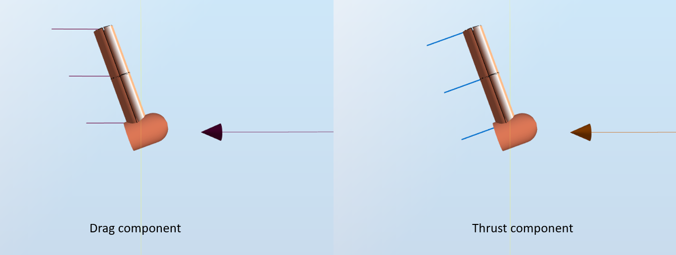
In the left image, the red vectors represent the drag force at each blade station. In the right image, the blue vectors represent the thrust force. A more detailed explanation of the different load components can be found in the
Velocity Triangle video.
The
rotor thrust
is the sum of the thrust forces of each station, which is then
$$F_T = dF_D\left(L_{I1}+L_{I2}+L_{I3}\right)\cos\theta = 151.38\text{ N}$$
Similarly, the component of the aerodynamic load that will contribute to the blade root bending moment is perpendicular to the blade, and is in this case the thrust force. The blade root bending moment will therefore be
$$M = (dF_D\cdot r_1\cdot L_{I1}+dF_D\cdot r_2\cdot L_{I2}+dF_D\cdot r_3\cdot L_{I3})\cos\theta =378.4\text{ Nm}$$
3.5 10 ms cone 2.5 deg
For this load case, the only change with respect to load case 1 is that the cone is now
$$\gamma = 2.5\text{ deg}$$
. When computing the drag force, the velocity to be considered is therefore
$$V = 10\cos\gamma$$
.
This yields
$$dF_D = \frac{1}{2}\rho D C_D (V\cos\gamma)^2 = 30.57\text{ N}\cdot{m}^{-1}$$
Similarly to load case 1, the magnitude of the force at the root will be
$$F = dF_D\left(L_{I1}+L_{I2}+L_{I3}\right) = 152.83\text{ N}$$
.
Contrary to the previous case, the drag load and the thrust component of each blade station are equal.
Therefore, the
rotor thrust is equal to the root force.
For the
blade root moment, we need to take again the component of the load that is perpendicular to the blade. In this case, this component will be
$$dT = dF_D\cos\gamma$$
. The blade root moment will the be
$$M = dF_D\cos\gamma\left(L_{I1}r_1+L_{I2}r_2+L_{I3}r_3\right) = 381.72\text{ Nm}$$
4 Results
A simulation of one second is run for each load case, both in
Dynamic and
Loads only, which results in 10 simulations. The test is considered passed if the results produced by Ashes lie within 0.5% of the analytical solution.
The report with the results can be found here