Tower shadow potential flow
This tests verifies that the implementation of the
Tower shadow in Ashes corresponds to the description in
Hansen (2008d). In order to verify the results, we compute the analytical solution for the aerodynamic loads that apply on the blades of a wind turbine under different configurations that include the tower shadow.
1 Test description
The following load cases are tested:
- No tower shadow
- Tower shadow
2 Model
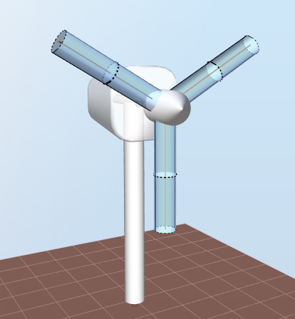
The model used for this test is shown in the figure below. We acknowledge that it is not the prettiest wind turbine ever, but it serves the purpose of this test.
We use the blade from the
Cylindrical blade test, which has a constant chordlength
$$c = 1\text{ m}$$
, and whose airfoils have a drag coefficient
$$C_D = 0.5$$
. The table below gives a summary of the relevant blade characteristics:| Blade aerodynamical station | Distance to root | Influence length |
| 1 |
$$r_1 = 0$$
|
$$L_{I1}=1.25\text{ m}$$
|
| 2 |
$$r_2 = 2.5\text{ m}$$
|
$$L_{I2} = 2.5\text{ m}$$
|
| 3 |
$$r_3 = 5\text{ m}$$
|
$$L_{I3} = 1.25\text{ m}$$
|
The default tower has a constant diameter
$$a= 0.5\text{ m}$$
. The distance between the axis of the tower and the
Aerodynamical reference point is
$$r = 3\text{ m}$$
.
Gravity loads are not applied and the wind density is
$$\rho = 1.225\text{ kg}\cdot{m}^{-3}$$
. The rotor is fixed.3 Analytical solution
For an incoming wind speed at the aerodynamical reference point
$$V$$
, the distributed drag force is given by
$$dF = \frac{1}{2}\rho c C_DV^2$$
The total force at the root of the blade is therefore
$$F = \Sigma_{i=1}^3dF\cdot L_{Ii}$$
The bending moment at the moment of the blade will be
$$M = \Sigma_{i=1}^3dF\cdot L_{Ii}\cdot r_i$$
To compute the effect of the tower on the incoming wind, Ashes uses
potential flow theory as suggested in
Hansen (2008d). The image below illustrates the polar coordinate system used to determine the incoming wind:
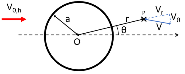
A detailed explanation of the coordinate system and wind components can be found in the
Potential flow tower shadow model document.
The radial and axial components of the incoming wind are given by
$$V_r = \left(1-\left(\frac{a}{r}\right)^2\right)|V_{0,h}|\cos\theta$$
and
$$V_\theta = -\left(1+\left(\frac{a}{r}\right)^2\right)|V_{0,h}|\sin\theta$$
where
$$|V_{0,h}|$$
is the magnitude of the undisturbed wind.3.1 No tower shadow
If no tower shadow is applied, the incoming wind will be equal to the undisturbed wind,
$$V = V_{0,h}=10\text{ m}\cdot{s}^{-1}$$
.
In this case the
root force will be
$$F = 153\text{ N}$$
and the
root bending moment will be
$$M = 383\text{ Nm}$$
.3.2 Tower shadow
For this load case, the tower and the blade are aligned, which implies
$$\theta = 180\text{ deg}$$
. This results in an incoming wind speed
$$V = 9.72\text{ m}\cdot{s}^{-1}$$
.
The
root force
will be
$$F = 145\text{ N}$$
and the
root bending moment
will be
$$M = 362\text{ Nm}$$
.4 Results
A simulation of five seconds is run. Since the analysis mode is
Loads only, the output from Ashes is constant. The test is considered passed if the results from Ashes lie within 0.05% of the analytical solution.
The report for this test can be found on the following link: