Buoyancy test
This test checks the values for the buoyancy components, see
Buoyancy
for details on the theory.
1 Test description
This test uses a cylinder floating in water. For different waves and initial conditions, the
Buoyancy loads
and
Buoyancy springs
from the
Total hydro loads sensor
are benchmarked against analytical solutions.
2 Model
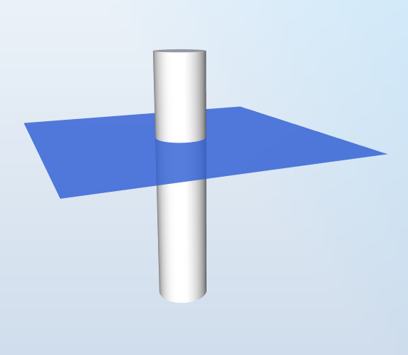
The model is illustrated in the figure below:

The model consists of a uniform circular cylinder. The diameter of the cylinder is
$$D = 6\text{ m}$$
and the thickness is
$$t = 0.060\text{ m}$$
. This gives an outer area
$$A = \pi(D/2)^2=28.27\text{ m}^2$$
and a structural area
$$A_S = \pi(D/2)^2 - \pi(D/2-t)^2=1.120\text{ m}^2$$
.
The cylinder is made of steel with a density
$$d = 8500\text{ kg}\cdot\text{m}^{-3}$$
. The length of the cylinder is
$$L = 30\text{ m}$$
, which gives it a mass
$$m_S = A_S\cdot L\cdot d = 285.5\text{ t}$$
. In addition, a point mass of
$$m_P = 195.18\text{ t}$$
is added at the lowest node of the structure, which gives a total mass of
$$m = m_S+m_P=580.69\text{ t}$$
The water density is
$$d_W = 1026.9\text{ kg}\cdot\text{m}^{-3}$$
.
The gravitational acceleration is
$$g=9.80665\text{ m}\cdot\text{s}^{-2}$$
3 Analytical solution
3.1 Draft 20 m
For this test, the initial draft of the cylinder is
$$l = 20\text{ m}$$
.
The mass of the displaced water in the initial position is thus
$$M_W=l\cdot A\cdot d_W$$
and the buoyancy force will be
$$F_B = g\cdot M_W=5694\text{ kN}$$
The simulation is run with
Loads only
, so the cylinder does not move.
3.2 Draft 20 m with waves
This test is the same as the previous one with the addition of linear regular waves of period
$$T = 10\text{ s}$$
and amplitude
$$A = 2\text{ m}$$
. The time-varying wave elevation at the center of the cylinder will thus be
$$\zeta(t) = A\sin(2\pi t/T)$$
. The buoyancy force will be
$$F_B(t) = g\cdot A\cdot d_W \cdot\left(l+\zeta(t)\right)$$
The simulation is run with
Loads only
, so the cylinder does not move.
3.3 Draft 20 m with waves two cylinders
This test is the same as the previous one, but a second floating cylinder is placed at a distance
$$D = 70\text{ m}$$
ahead of the first cylinder, as shown in the figure below.

The wave elevation at the second cylinder is thus
$$\zeta_2(t) = A\sin(2\pi t/T+k\cdot D)$$
where
$$k$$
is the wave number and is equal to
$$\omega^2/g$$
and
$$\omega = 2\pi/T$$
.
The buoyancy force will be the sum of the buoyancy forces on the two cylinders, equal to
$$F_B(t) = g\cdot A\cdot d_W \cdot\left(2l+\zeta(t)+\zeta_2(t)\right)$$
Note:
the buoyancy force will not vary with the motion of the floater, as it is computed with the initial position of the floater. It will only change if parts of the structure are subjected to changes in the water elevation due to waves.
3.4 Draft 20 m sine motion
In this test, one cylinder is forced to move vertically sinusoidally with an amplitude of 2 meters and a period of 10 seconds. There are no waves.
Since the cylinder moves in the vertical direction, it will be subjected to loads from
Buoyancy springs.
As explained in the
Buoyancy
section, the loads from buoyancy springs can be exporessed as
$$P_-(t) = -A\cdot L(t)\cdot g\cdot d_w$$
, where
$$L(t)$$
is the vertical displacement of the cylinder equal to
$$L(t)=2\sin(2\pi t/10)$$
.
This yields
$$P_-(t)=569\cdot\sin(2\pi t/10)$$
3.5 Draft 21 m
A static simulation is run with the model from the previous load case with no waves and a draft of 21 m. This simulation will find the static equilibrium of the cylinder given the initial conditions.
The total mass of the cylinder is
$$m=580.69\text{ t}$$
, which gives a total weight
$$P=-mg=-5694\text{ kN}$$
. This is equal to the buoyancy force of the load case with a draft of 20 m, which means that the equilibrium position of this cylinder happens when the draft is equal to 20 m. Therefore, for the present load case where the initial draft is
$$l=21\text{ m}$$
, we expect the cylinder to rise by 1 m.
The mass of displaced water in the initial position is thus
$$M_W=l\cdot A\cdot dw$$
and the buoyancy force will be
$$F_B=g\cdot M_W = 5978\text{ kN}$$
.
$$P_-=-A\cdot L\cdot g\cdot d_W$$
, where
$$L$$
is the vertical displacement of the cylinder and is expected to be 1 m. This yields
$$P_- = -285 \text{ kN}$$
Note that
$$P_-+P+F_B=0$$
. This is expected since the cylinder is in equilibrium.
4 Results
For the first two load cases, a simulation of 30 seconds is run. The test is considered passed if the last 20% of the time series produced by Ashes is within 0.5% of the analytical solution
For the static load case, the test is considered passed if the results produced by Ashes are within 0.5% of the analytical solution.
The reports for this test can be found on the following links: