Aerodynamic Loads on Support section elements - Aero drag loads
This section deals with the aerodynamic loads on non-blade elements. For aerodynamic loads on the blades, see
BEM algorithm.
In Ashes, aerodynamic loads are applied on any element of the support section that has a
non-zero drag coefficient. The aerodynamic loads on an element are computed with the drag term of the Morison equation (
Morison et al. (1950)):
$$F_{aero}=\frac{1}{2}\rho V_P^2C_DA$$
where
-
$$\rho$$is the air density, that can be changed in the Atmosphere part
-
$$V_P$$is the component of the incoming wind perpendicular to the axis of the cylinder
-
$$C_D$$is the drag coefficient
-
$$A$$is the cross sectional area, i.e. the area of the element facing the wind projected onto a plane perpendicular to the incoming wind. For example, for a circular cylindrical element of length$$L$$and diameter$$D$$, the cross sectional area is$$A=L\cdot D$$.
The aerodynamic drag load is illustrated in the figure below:
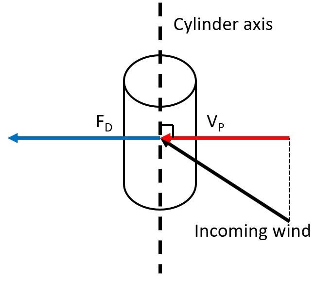
Note: the aerodynamic drag load only gives a load perpendicular to the axis of the element. If the wind is not perpendicular to the axis of the element, only the component perpendicular to the elemnt axis is taken in the drag equation. This means that elements whose axis is aligned with the wind will not experience any drag load.
The drag coefficient can be changed
- for Parameter based support structures, in the Aerodynamics tab of the Analysis parameters dialog. Note: the same drag coefficient will be applied for all elements of the support section (including monopile and floater)
- for Support sections from file, each Cross section has its own drag coefficient, as defined in the Cross section Keywords.
Note: the velocity of the element (as aresult of tower motion for example) is not taken into account when computing the aerodynamic drag. The drag load therefore only comes from the incoming wind and not from the velocity of the element.
It is possible to add a sensor on the drag loads by following the procedure described in the
Individual load sensor section. This sensor will also provide the wind velocity used to compute the aerodynamic load, i.e. the component of the incoming wind perpendicular to the element axis.
Note:
in Ashes, the loads are generally calculated on the elements but applied on the nodes defining the element. For the aerodynamic drag load for example, the load on an element is split in two and applied to the two nodes of the element. Therefore, the aerodynamic load on one node of an element will correspond to only
half
of the aerodynamic load on that element.