Spring test
1 Test description
This test uses a model composed of two nodes and one element. One node is attached to a
linear spring
(translational or rotational). A load (force or moment) is applied to that node and the node displacement is observed. This test is carried out both with the linear and nonlinear solvers (see
Time domain simulation).
Aerodynamic
loads
and
gravity
loads
are disabled.
Several load cases are run, with springs and loads in all 6 degrees of freedom
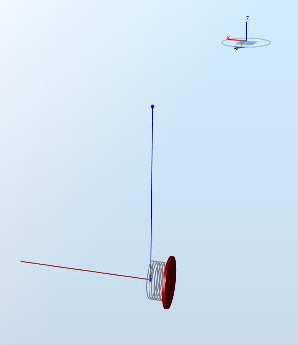
The figure below illustrates the model with a spring in the x-direction. The red vector represents a force in the x-direction.
2 Analytical solution
For a degree of freedom
$$i$$
, the displacement is equal to
$$\delta_i=\frac{P_i}{K_i}$$
where
-
$$P_i$$is the load in the$$i^{th}$$degree of freedom, in$$\text{N}$$for forces and$$\text{Nm}$$for moments
-
$$K_i$$is the stiffness in the$$i^{th}$$degree of freedom, in$$\text{N}\cdot\text{m}^{-1}$$for translational springs and$$\text{Nm}\cdot\text{rd}^{-1}$$for rotational springs
Note: the rotational displacement of a node in Ashes is given in
degrees
-
the forces along the x, y and z axes,
$$F_x, F_y$$and$$F_z$$, in$$\text{kN}$$
-
the moments around the x, y and z axes,
$$M_x, M_y$$and$$M_z$$, in$$MNm$$
-
the stiffnesses along the x, y and z axes,
$$K_{11}, K_{22}$$and$$K_{33}$$, in$$\text{kN}\cdot\text{m}^{-1}$$
-
the stiffnesses around the x, y and z axes,
$$K_{44}, K_{55}$$and$$K_{66}$$, in$$\text{MNm}\cdot\text{rd}^{-1}$$
-
the displacements of the node on the spring along the x, y and z axes
$$u,v$$and$$w$$, in$$\text{m}$$
-
the rotational displacements of the node on the spring along the x, y and z axes
$$ru, rv$$and$$rw$$, in$$\text{deg}$$
Note: the displacement is only compared to an analytical solution for the degrees of freedom for which a stiffness is provided and a load is applied. For other degrees of freedom, the displacement will not be in general 0, but is not used in this test.
| Load case name | Load | Stiffness | Displacement | |||||||||||||||
|
$$F_x$$
|
$$F_y$$
|
$$F_z$$
|
$$M_x$$
|
$$M_y$$
|
$$M_z$$
|
$$K_1$$
|
$$K_2$$
|
$$K_3$$
|
$$K_4$$
|
$$K_5$$
|
$$K_6$$
|
$$u$$
|
$$v$$
|
$$w$$
|
$$ru$$
|
$$rv$$
|
$$rw$$
| |
| Translational x-direction | 100 | 0 | 0 | 0 | 0 | 0 | 5 000 | 0 | 0 | 0 | 0 | 0 | 0.02 | - | - | - | - | - |
| Translational x-direction, negative force | -200 | 0 | 0 | 0 | 0 | 0 | 5 000 | 0 | 0 | 0 | 0 | 0 | -0.04 | - | - | - | - | - |
| Translational y-direction | 0 | 100 | 0 | 0 | 0 | 0 | 0 | 6 000 | 0 | 0 | 0 | 0 | - | 0.0167 | - | - | - | - |
| Translational y-direction, negative force | 0 | -200 | 0 | 0 | 0 | 0 | 0 | 6 000 | 0 | 0 | 0 | 0 | - | -0.0333 | - | - | - | - |
| Translational z-direction | 0 | 0 | 10 | 0 | 0 | 0 | 0 | 0 | 1 000 | 0 | 0 | 0 | - | - | 0.01 | - | - | - |
| Translational z-direction, negative force | 0 | 0 | -25 | 0 | 0 | 0 | 0 | 0 | 1 000 | 0 | 0 | 0 | - | - | -0.025 | - | - | - |
| Translational xyz-direction | 200 | 100 | -25 | 0 | 0 | 0 | 5 000 | 5 000 | 1 000 | 0 | 0 | 0 | 0.04 | 0.02 | -0.025 | - | - | - |
| Rotational x-direction | 0 | 0 | 0 | 10 | 0 | 0 | 0 | 0 | 0 | 50 000 | 0 | 0 | - | - | - | 0.01146 | - | - |
| Rotational y-direction | 0 | 0 | 0 | 0 | 10 | 0 | 0 | 0 | 0 | 0 | 50 000 | 0 | - | - | - | - | 0.01146 | - |
| Rotational z-direction | 0 | 0 | 0 | 0 | 0 | 10 | 0 | 0 | 0 | 0 | 0 | 50 000 | - | - | - | - | - | 0.01146 |
In addition to these 9 load cases, another set of 9 load cases with the same input is run with the linear solver instead of the nonlinear one. It is expected that the results will be the same.
All the translational tests are also repeated using a 6x6 spring matrix with the corresponding stiffness, with the nonlinear solver. Again, the results are expected to remain the same as with the simple linear spring
3 Results
In Ashes, the loads are applied with a
ramp-up, i.e. they start at 0 and are progressively increased until their value (see
Analysis). Therefore, the output produced by Ashes will show a ramp-up period as well.
A test is considered passed when all values of the
last second of the results produced by Ashes are within
0.01% of the analytical solution.
The report for this test can be found on the following link: