The outputs of the Blade aerodynamical station sensor are the same as the Blade [Span] sensor, but their evolution in time is given, rather than accross the blade.
Blade aerodynamical station sensor
A blade is divided into a number of
Blade aerodynamical station, where aerodynamic properties are evaluated. The number of blade aerodynamical stations and their locations is defined in the
Blade shape file.
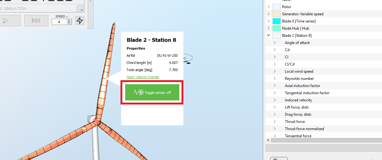
The
Blade aerodynamical station sensor enables to track how the different output at the
Blade aerodynamical station evolve in time. It can be opened by right-clicking on a blade aerodynamical station and toggling the sensor on, as shown in the following picture:
The
Blade aerodynamical station sensor has the following fields, computed with the
BEM algorithm:
| Field | Unit | Description |
| Angle of attack | deg | The angle bewteen the relative wind and the chordline |
| Cd | - | Drag coefficient |
| Cl | - | Lift coefficient |
| Cm | - | Moment coefficient |
| Cl/Cd | - | Ratio of lift over drag coefficients |
| Local wind speed | m.s-1 | Wind speed at the station in the horizontal plane. Note that this is only the magnitude of the wind at the blade aerodynamical stations: it does not include the effects of tilt, yaw, cone angles or the deflections of the blade |
| Relative wind speed | m.s-1 | Magnitude of the sum of the wind velocity, rotational velocity and any structural velocity at the blade station, relative to the airfoil |
| Reynolds number | - | Reynolds number at the station, calculated with the chordlength, the relative velocity and the kinematic viscosity as defined in the Environment part |
| Mach number | - | Mach number at the station, calculated as the ratio between the Relative velocity and the speed of sounds (taken as 343 m.s -1) |
| Axial induction factor | - | as calculated with the BEM method |
| Tangential induction factor | - | as calculated with the BEM method |
| Induced velocity | m.s-1 | Induced velocity in the direction of the incoming wind, as computed by the BEM solver (axial induction) |
| Tangential induced velocity | m.s-1 | Induced velocity in the rotational direction of the blade aerodynamic station, as computed by the BEM solver (tangential induction) |
| Lift force, distr. | N.m-1 | Aerodynamic force in the direction perpendicular to the incoming wind (lift), per unit length |
| Drag force, distr. | N.m-1 | Aerodynamic force in the direction of the incoming wind (drag), per unit length |
| Pitching moment, distr. | Nm.m-1 | Aerodynamic moment around the pitch axis, per unit length |
| Thrust force, distr. | N.m-1 | Aerodynamic force in the wind direction, per unit length of blade element |
| Thrust force normalized, distr. | - | Distributed thrust force divided by ρ⋅U2⋅chord, giving a non-dimensional distributed thrust coefficient |
| Torque force, distr. | N.m-1 | Aerodynamic force in the direction of rotation of the blade, per unit length |
| Torque force normalized, distr. | - | Distributed torque force divided by ρ⋅U2⋅chord, giving a non-dimensional distributed torque coefficient |
| Steady BEM iterations | - | Number of iterations performed by the steady BEM solver at this blade station |
| Deflection (out of plane) | m | Out-of-plane deflection of the blade at this station |
| Deflection (in-plane) | m | In-plane isplacement of the blade aerodynamical station. |
| Moment (magnitude) | Nm | Magnitude of the bending moment |