Turbulent wind tool
Ashes is capable of reading both full-field turbulent wind fields created with NREL's TurbSim and the IEC Turbulence generator for Mann turbulence
. If you are familiar with TurbSim and/or the IEC Turbulence Generator and already know how to generate turbulent wind files, you can directly use them in Ashes in the
Turbulent wind parameter.
If you need to generate turbulent wind files, Ashes provides a GUI for that purpose. To open the turbulent wind tool, click the
 icon as shown in the picture below:
icon as shown in the picture below:
1 Generating a turbulent wind file
Clicking on the turbulent wind tool icon opens the following window:
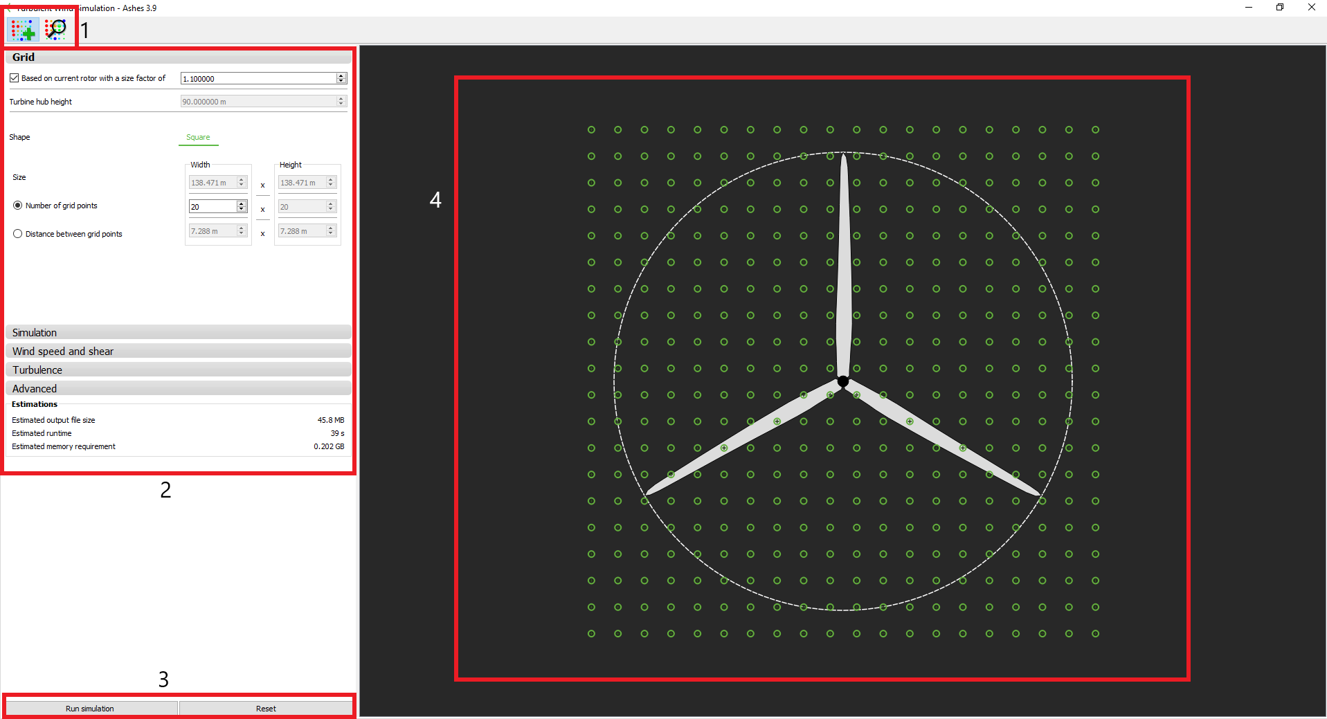
The different parts and functionalities of this window are listed below:
-
Generate/ investigate turbulent wind: these icons enable you to switch between the turbulent wind generator
 and the turbulent wind viewer
 (see below)
 - Turbulent wind parameters: all parameters that define the turbulent wind field generation are defined here. The next paragraph specifies the functionality of each parameter. Below the parameters, you can see an estimate of the size, time and memory required to run the generation of the field.
- Run/ reset: clicking the Run button starts the turbulent wind field generation. Clicking the Reset button will reset the parameters of the Grid, Simulation and Wind spee and shear to their default value
- Grid preview: this area shows you a transversal cut of the turbulent wind field. Each green circle represents a grid point, allowing you to preview the size of the grid compared to the rotor.
Note: you will only see a preview of the rotor if a model with a rotor is open.
1.1 Turbulent wind generation parameters
An overview of the parameters that define the generation of the turbulent wind field is given below. For a more detailed description of the parameters, please refer to the TurbSim User's Guide, available here:
https://nwtc.nrel.gov/system/files/TurbSim.pdf
1.1.1 Grid
- Based on current rotor: if a model with a rotor is loaded, it is possible to specify the transverse dimensions of the turbulent wind field based on the size of the rotor. The turbulent wind field will the be a square which sides have the length of the rotor diameter multiplied by the Size factor. It is important to have a turbulent wind field larger than the rotor to account for the displacements of the turbine, especially for floaters. If during the simulation the rotor moves out of the turbulent wind field, the simulation will stop and display an error.
- Turbine hub height: if the size of the turbulent wind field is not based on the current rotor, you will have to specify the turbine hub height. This will be the location of the center of the grid.
- Shape: if the size of the turbulent wind field is not based on the current rotor, you can specify the field to be a square or a rectangle. If the field is based on the rotor size, only a square filed can be defined
- Size: the size of each dimension of the turbulent wind field. If the turbulent wind field is based on the rotor, you can modify its size by changing the Size factor
- Number of grid points: number of grid points in each direction of the turbulent wind field.
-
Distance between grid points:
distance between grid points in each direction of the turbulent wind field.
Note: when having selected the Mann turbulence model, the number of grid points must be of power of two (2, 4, 8, 16 etc.) in both dimensions.
Note: the grid points are always evenly distributed accros both dimensions of the turbulent wind field. You can only specify either the Number of grid points or the Distance between grid points.
1.1.2 Simulation
- Timelength: duration of the turbulent wind field
-
Time step: time step for the turbulent wind field. The number of grid points in the wind direction is then the duration divided by the time step
Note: TurbSim will add extra grid points at the end of the turbulent wind field to ensure that the field covers the rotor despite the motions of the turbine. Therefore, the total duration of the turbulent wind field is always a bit larger than the specifired duration. For more details, please refer to the TurbSim User's Guide, available here: https://nwtc.nrel.gov/system/files/TurbSim.pdf. In Ashes, once the turbulent wind field is over, the wind will become uniform with a speed equal to the average ot the turbulent wind - Seed: by default, the seed is random, which means that every realization of a turbulent wind field with a given set of parameters will be different. In order to reproduce a turbulent wind field the seed can be User defined.
Note: when having selected the Mann turbulence model, the number of grids in timewise direction must be of power of two. ASHES will automatically adjust the time step to assure this.
1.1.3 Wind speed and shear
- Average wind speed at hub height: this is the targeted average or mean wind speed at hub height.
- Flow angles: mean vertical and horizontal flow angles of the turbulent wind field
- Shear: this enables you to have a vertical shear in the turbulent wind field. The shear is calculated with a power law (see Wind profile power law). If Shear is selected, the exponent of the power law can be either set by default (to a value of 0.2) or set by the user
- Surface roughness: this is a measure of the roughness of the surface terrain. It is used to compute the wind profile.
1.1.4 Turbulence
- Turbulence model: the different turbulence models available in TurbSim as well as the Mann turbulence model can be selected here. For more details about the different models please refer to the TurbSim User's Guide, available here: https://nwtc.nrel.gov/system/files/TurbSim.pdf or to the Thomsen (2006): https://nanopdf.com/download/the-spectra-in-iec61400-1-ed-3-is-in-inertial-subrange_pdf
- Alfa times epsilon: This parameters scales the intensity of the turbulence. For further information, see Thomsen (2006) Appendix A: https://nanopdf.com/download/the-spectra-in-iec61400-1-ed-3-is-in-inertial-subrange_pdf
- L: The L variable in the Mann turbulence model, corresponding to 0.7-0.8 Λ in IEC61400-1 ed3.
- Gamma: The parameter Gamma is similar to γ = 3.9 in IEC61400-1 ed3.
-
High frequency compensation:
Set to true of you want high frequencies to be compensated.
The parameter Gamma is similar to3.9in IEC61400-1 ed3The parameter Gamma is similar to3.9in IEC61400-1 ed3The parameter Gamma is similar to3.9in IEC61400-1 ed3 - Turbulence intensity: the turbulence intensity can either be defined by the user or computed for a class A, B or C according the IEC-61400-3-1 (2019) standard.
1.1.5 Advanced
Different files can be output at the end of the generation of the turbulent wind field. For a detailed decription of what each of these files do,
please refer to the TurbSim User's Guide, available here:
https://nwtc.nrel.gov/system/files/TurbSim.pdf
1.2 Running the generation of the turbulent wind field
Once all parameters have been set, click the
Run button to start the generation of the turbulent wind field. After entering the name and destination folder, a pop-up window will display the progress of the computation. If you selected a TurbSim turbulence model, three files will be created with the same name:
- a .inp file containing all the input of the computation. This file is directly readable by the standalone version of TurbSim
- a .sum file containing a summary of the computation. Here you can find the obtained mean wind speed at different locations, turbulence intensities, grid sizes, etc.
-
a
.wnd file containing the actual turbulent wind field. This file is in binary form
If you selected Mann turbulence, four files will be created with the names:
- three .bin files, one for each dimension of the turbulent wind grid: _u, _v, _w.
- one .txt file containing the input to the IEC Turbulence Generator.
Once the computation is over, you will be asked whether you want to load the turbulent wind field that was generated for investigation. Clicking
Yes will open the turbulent wind field viewer described in the next section.
2 Turbulent wind field viewer
The turbulent wind filed viewer enables you to visualize any turbulent wind field that was generated by TurbSim (not by the IEC Turbulence Generator yet). The following picture shows the turbulent wind field viewer
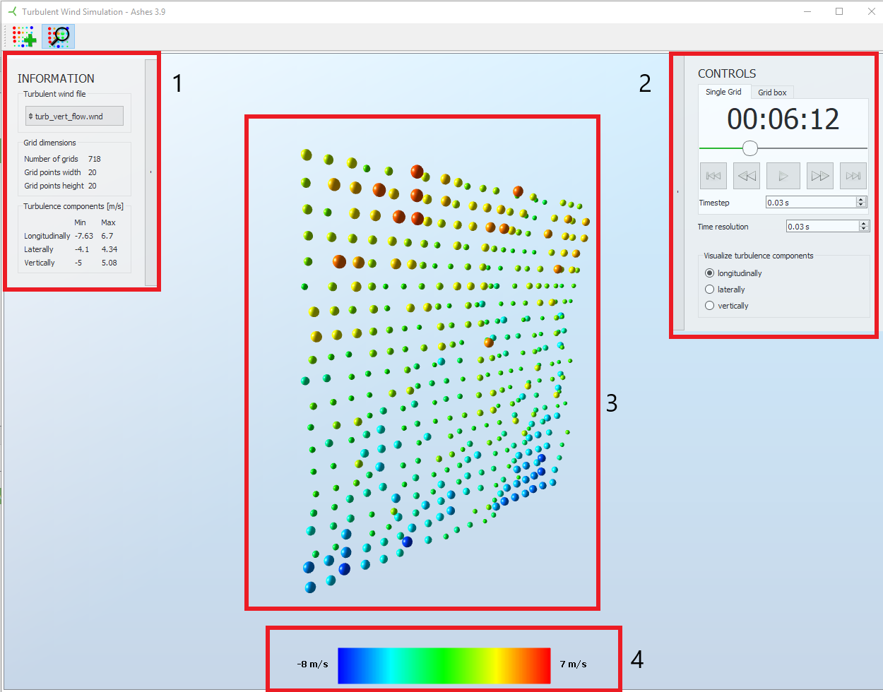
The different parts and functionalities of the viwere are listed below:
- Information: this pane gives you a summary of the turbulent wind field currebtly being visualized. Clicking the button with the file name enables you to select another turbulent wind field.
- Controls: this pane enables you to navigate though and to visualize different components of the turbulent wind field. Select the Grid box view to visualize many grids simultaneously
- Visualization area: the different components at the different grid points are shown in this area. The value of the turbulence intensity at each grid point is visualized by the color, the size of the sphere and the displacement from the vertical plane
- Legend: the color bar shows you the correspondance between the colors displayed and the turbulence intensity.
Note: the values displayed in the turbulent wind field viewer correspond to turbulence intensity and not to absolute wind speed.