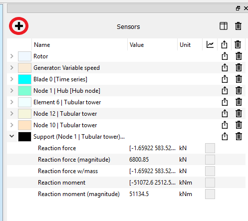
Adding a sensor
The
list of added sensors
appears on the upper right pane, the
Sensors
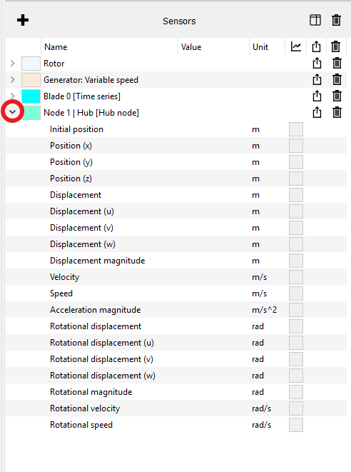
pane. Click the small arrow on the left of the sensor name to see what
Fields are provided by a given sensor. The image below shows the default fields in the
Hub node
sensor.
Note: it is possible to choose which fields are displayed in each sensor, see
Customise sensor fields.
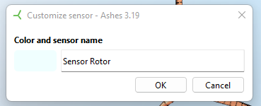
The field containing the name of the sensor is editable. Note that if you export the sensor data, the name of the file ontaining the data from the fields of the sensor will be the name that you have chosen (see
Export the data).
There are different ways to add sensors, listed below.
1 Part sensors
Some parts have a dedicated sensor. You will recognize them because of the
 icon just to their right on the parts pane, as shown in the image below.
icon just to their right on the parts pane, as shown in the image below.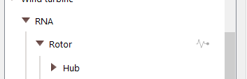
By clicking the
icon you will toggle on the sensor and add it to the sensor list. When a sensor is selected, its icon will turn green, as seen in the image below.
icon you will toggle on the sensor and add it to the sensor list. When a sensor is selected, its icon will turn green, as seen in the image below.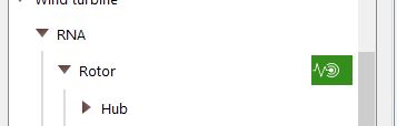
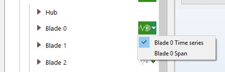
Some parts can have different types of sensors. On each blade, for example, it is possible to select two types of sensors:
-
Blade [time]
gives the variation of a parameter as a function of time
- Blade [span] gives the variation of a parameter along the blade
For sensors with multiple options, the icon has a small arrow that opens a dropdown menu enabling you to select the relevant sensor, as shown in the image below.
2 Element / node / support sensors
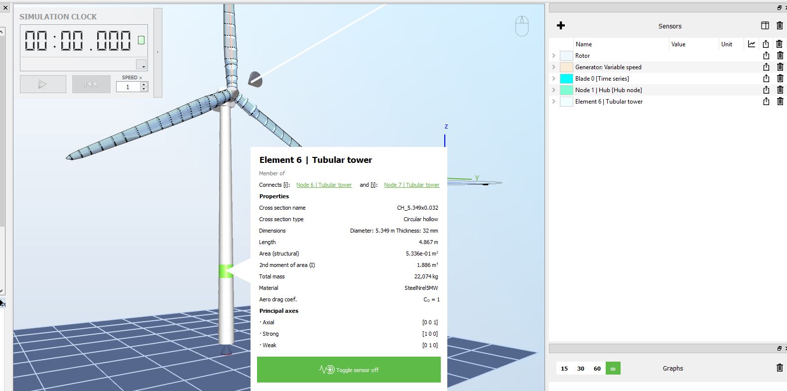
To add this type of sensor, right-click on the element/node/support on the model and toggle the sensor on. The image below shows how to place a sensor on element 6 on the tubular tower.
In the default visualization mode, the nodes are not visible as they are hidden by the structure. In order to see the nodes and be able to toggle a sensor on, go on wireframe mode by clicking the
 icon in the
Top ribbon
(see
Simulation window).
icon in the
Top ribbon
(see
Simulation window).
icon in the
Top ribbon
(see
Simulation window).
Three types of sensors can be toggled on for nodes:
-
the default sensor outputs on the position and motion of the node
-
the loads sensor outputs the excitation loads on the node
-
the kinematics sensor outputs the wave and wind kinematics (when applicable) at the node position. Note that the nodes can change their position over time, which means that the position where the kinematics are evaluated will change.
3 Load sensors
It is possible to add sensors on the loads as well: right-click on the vector representing the load and toggle the sensor on.
This does not apply to aerodynamic loads on the blade elements. For such loads, open the
Velocity triangle.
4 Special sensors
A number of special sensors can be added by clicking on the icon shown in the image below.
A description of these sensors is given in the
Sensor list.