Blade structure offsets
1 Test description
This test uses a simple blade composed of one airfoil to verify the influence of the elastic, shear and mass offsets. These offsets are defined in the
Blade structure file. For the test we take the characteristics of the half-blade section of the
DTU 10-MW. The blades do not rotate. The gravitational acceleration is
$$g = 9.80665\text{ m}\cdot{s}^{-2}$$
.
The blade has a projected length of 10 meters (see
Blade length) and is divided into 4 elements.
The offsets are defined as follows:
|
ElasticCenterOffsetX
$$e_x$$
|
ElasticCenterOffsetY
$$e_y$$
|
MassCenterOffsetX
$$m_x$$
|
MassCenterOffsetY
$$m_y$$
|
ShearCenterOffsetX
$$s_x$$
|
ShearCenterOffsetY
$$s_y$$
|
| 0.7349 m | 0.0189 m | 0.5665 m | 0.025 m | 1.1275 m | 0.0611m |
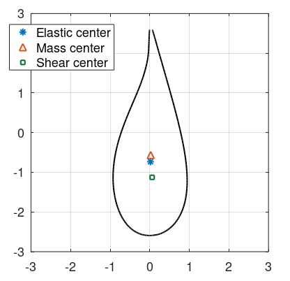
The offsets are given from the
chordline mid-point, and are positive towards the leading edge and towards the suction side. The airfoil is shown in the figure below:
To assess wether the offsets are applied correctly, we apply gravity loads and analyse the value of the
Root torque of the blade, from the
Blade [Time] sensor.
Note that in this model, the first 2 nodes (i.e. closest to the root) have no structural offsets. Therefore, the element between nodes 2 and 3 will appear misaligned with the others, as shown in the figure below:
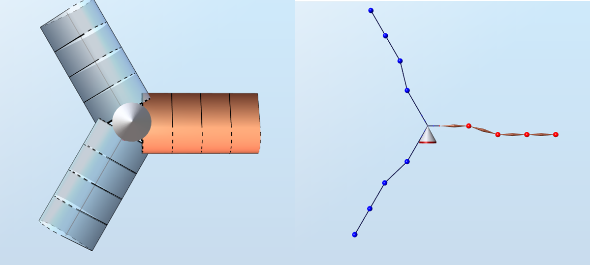
The pitch axis is aligned with the first element and aligned with the chordline midpoint of all the aerodunamical blade stations.
For this test, the two innermost elements do not have any mass.
1.1 Weight of the elements
In this set of tests we will check the torque produced by the center of mass eccentricity. Therefore, we need to evaluate the weight of each element.
The two outermost elements have a lenght
$$l_o = 2.5\text{ m}$$
, and the linear mass of the blade is
$$m = 425\text{ kg}\cdot{m}^{-1}$$
, so the weight of teach element is
$$W_o = m\cdot l_o\cdot g = 10.419\text{ kN}$$
.2 Analytical results
2.1 Elastic offset
For this test, the azimuth angle is set to 90 degrees, so that the pitch axis of blade 1 is aligned with the x-axis, as shown in the figure below:
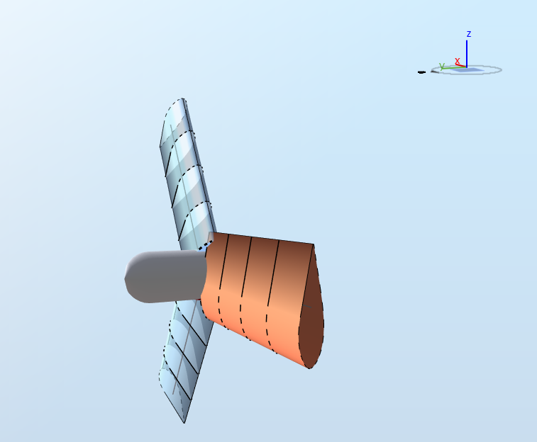
Only gravity loads are applied (i.e. no aerodynamic loads). First we compute the force at the support of blade 1, which is the
root force output from the
Blade [Time] sensor).
The
root force
will be the sum of the weights of the two non-massless elements,
$$F = 2\cdot W_o=20.855\text{ kN}$$
. The root force will be the same for all the tests presented in this document.
We now look at the
root torque
from the
Blade [Time] sensor. The root torque is the moment along the
Pitch axis.
In this test, only the
elastic center is applied, so the root torque will be the consequence of the weight of the blade and the elastic center offset. Since the gravity acts along the chordline, only the offset perpendicular to the chordline,
$$e_y$$
, is relevant. Since
$$e_y$$
is positive towards the suction side, the weight will produce a torque
positive in the x-direction, which will create a response torque at the root
positive along the pitch axis. The
root torque will thus be
$$T = F\cdot e_y = 0.394\text{ kN}$$
More details about the sign of the
root torque can be found in the
Blade [Time] sensor document.
2.2 Elastic offset 45 pitch
For this test, the blades are pitched
$$\theta = 45\text{ deg}$$
, as shown in the figure below.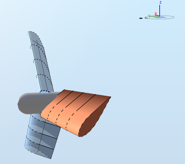
The distance between the elastic center and the axis upon which gravity acts that goes through the pitch axis is now
The root torque is therefore:
$$d = e_y\cos\theta-e_x\sin\theta$$
The root torque is therefore:
$$T = F\cdot d=-10.559\text{ kNm}$$
2.3 Mass offset
In this test, the pitch of the blades is set back to 0 degrees but the loads are applied on the mass center.
The torque will therefore be
$$T = F\cdot m_y = 521.4\text{ Nm}$$
2.4 Mass offset 45 pitch
In this test, the pitch of the blades is
$$\theta = 45\text{ deg}$$
and the gravity loads are applied on the mass center.
The distance between the mass center and the axis upon which gravity acts that goes through the pitch axis is now
$$d = m_y\cos\theta - m_x\cos\theta$$
.
The
root torque is therefore
$$T = F\cdot d = -7.985\text{ kNm}$$
3 Results
A simulation of five seconds is run. The test is considered passed if the last 20% of the times series from Ashes lie within 0.05% of the analytical solution.
The report for this test can be found on the following link: