Blade Structure file
Each blade is divided into a number of structural elements that are used in the finite element solver. These elements are defined by two nodes. The
Blade structure file defines the position of each of these nodes and the structural properties of each element. An element will use the structural properties input to the innermost of its two nodes (i.e. the node closest to the blade root).
The following properties can be input:
| BlFract | (-) | distance from the root to the node, normalized against the blade length |
| StrcTwist | (deg) | this will determine the direction of the stiffnesses. For a straight blade with no cone, an angle of 0 means the edgewise stiffness will be in the rotor plane. More info here Blade structure twist. Generally the same as the Blade shape twist |
| BMassDen | (kg/m) | distributed blade section mass per unit length |
| FlpStiff | (Nm²) | flapwise section stiffness, given about the principal structural axis of the cross section oriented by the structural twist angle |
| EdgStiff |
(Nm²)
|
edgewise section stiffness, given about the principal structural axis of the cross section as oriented by the structural twist angle |
| GJStiff | (Nm²) | blade torsion stiffness |
| EAStff | (N) | blade extensional stiffness |
| FlpIner | (kg m) | distributed flapwise section inertia, given about the principal structural axis of the cross section as oriented by the structural twist angle |
| EdgIner | (kg m) | distributed edgewise section inertia, given about the principal structural axis of the cross section as oriented by the structural twist angle |
| ElasticCenterOffsetX | (m) | offset of the elastic center with respect to the chordline midpoint, along the chord line, positive towards the leading edge |
| ElasticCenterOffsetY | (m) | offset of the elastic center with respect to the chordline midpoint, prependicular to the chord line, positive towards the suction side |
| MassCenterOffsetX | (m) | offset of the mass center with respect to the chordline midpoint, along the chord line, positive towards the leading edge |
| MassCenterOffsetY | (m) | offset of the mass center with respect to the chordline midpoint, perpendicular to the chord line, positive towards the suction side |
| ShearCenterOffsetX | (m) | offset of the shear center with respect to the chordline midpoint, along the chord line, positive towards the leading edge |
| ShearCenterOffsetY | (m) | offset of the shear center with respect to the chordline midpoint, prependicular to the chord line, positive towards the suction side |
| GShearAreaFlapwise | (N) | Shear modulus times shear area in the flapwise direction |
| GShearAreaEdgewise | (N) | Shear modulus times shear area in the edgewise direction |
Note: the first node of the blade is always located on the pitch axis. No structural offsets are allowed for that node. If a non-zero value is set for these offsets, you will get the
All offsets have to be zero at the root error.
Note: the last node is only used to define the location of the tip (in case there are structural offsets). All other parameters will be ignored
The position of the structural centers (i.e. the Elastic, Mass and Shear centers) will depend on the
BlCrvAC
and
BlSwpAC
parameters of the
Blade shape file and the offset parameters in the
Blade structure file.
To understand how these are linked, the following example shows how to obtain the position of the
Elastic center step by setp.
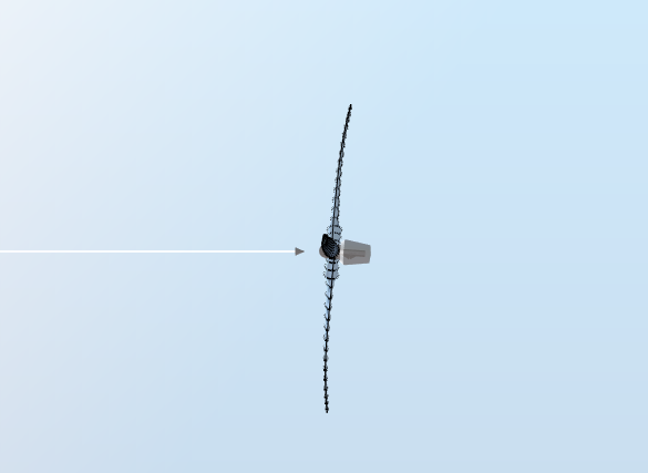
1. Defining the
Pitch axis
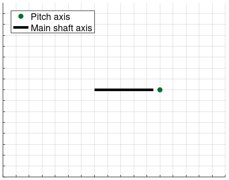
This is equivalent to seeing the blade from the tip towards the root, as illustrated in the figure below. The white vector represents the wind direction
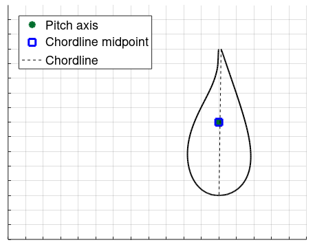
2. Placing the
Chordline midpoint on the pitch axis. The
Blade aerodynamical station is perpendicular to the pitch axis.
3 Offsetting the chordline midpoint
BlCrvAC and
BlSwpAC, which define the prebending of the blade.
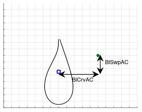
Note: in this example, both
BlSwpAC
and
BlCrvAC are negative, as is commonly the case for conventional prebent blades
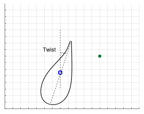
Note: in this example, the structure twist angle is positive.
5. Pitching the airfoil around the pitch axis
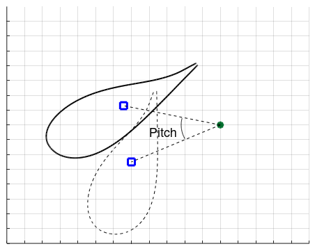
Note: in this example, the pitch angle is positive.
6. The
Elastic center
is offset from the chordline midpoint by
- ElasticCenterOffsetX along the chordline, where positive values are towards the leading edge
- ElasticCenterOffsetY perpendicular to the chordline, where positive values are towards the suction side
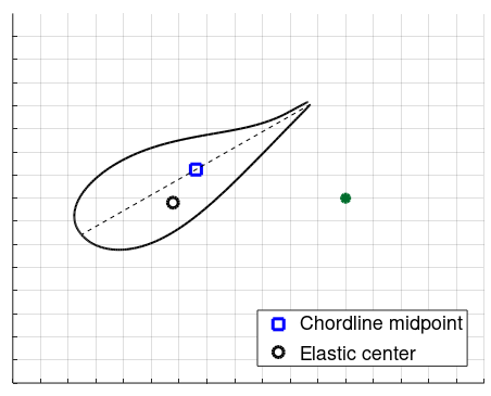
The figure below is a zoom of the previous one.
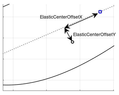
Note: in this example, both
ElasticCenterOffsetX and
ElasticCenterOffsetY are positive.