Maximum stress
1 Test description
This test checks that the results from the
ULS sensor
are correct. The maximum stress computed by Ashes is compared to the analytical solution.
2 Model
This test uses the
Tubular tower only
template.
The csv file to run this test can be downloaded from
here
.
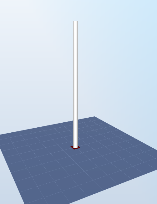
The model is shown in the figure below:

The model has a homogeneous circular hollow cross section of diameter
$$D = 3.87\text{ m}$$
and thickness
$$t = 0.025\text{ m}$$
. The length of the beam is
$$l = 100\text{ m}$$
and it is fixed onto the floor.
The material is steel, with an Elastic modulus
A force
$$E = 2.1\cdot10^{11}\text{ Pa}$$
A force
$$F = 400\text{ kN}$$
is applied at the tip of the y-direction.
A static analysis is run for this test.
3 Analytical solution
With these input, it is expected that the maximum stress will occur at the bottom of the structure. The bending moment at the bottom will be
$$M = F\cdot l=40\text{ MNm}$$
. For a cylindrical cross section, the neutral axis goes trough the center of the circular cross section. Therefore, the distance from the neutral axis from the external side of the cross section is
$$c = D/2=1.935\text{ m}$$
.
The second moment of area of the cross section is
$$I = \pi/4\left[(D/2)^4-(D/2-t)^4\right]=0.5581\text{ m}^4$$
The
maximum normal stress
will thus be
$$\sigma_{max}=\frac{M\cdot c}{I}=138\text{ MPa}$$
From this input, it is also possible to compute the deflection of the tip, which will be
$$d = \frac{F\cdot l^3}{3EI} = 1.13\text{ m}$$
4 Results
The test is considered passed if both the maximum normal stress and the tip deflection are within 0.1% of the analytical solution.
The report for this test can be dowloaded from the following link: