OC3 Phase I load case 1.2
We have separated this load case from the rest of the OC3 Phase I benchmarks because this load case compares eigenfrequencies, which we compare differently than the load cases that compare time series.
1 Test description
In this load case, we compare the eigenfrequencies of the model between aeroelastic software. The results are given in figure 6 in
Jonkman et al. (2010k).
2 Model
The model is the Offhsore NREL 5-MW reference wind turbine, which corresponds to the offshore template in Ashes.
3 Benchmarks
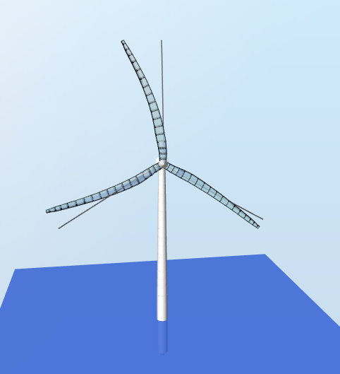
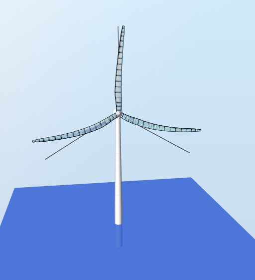
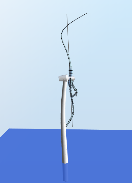
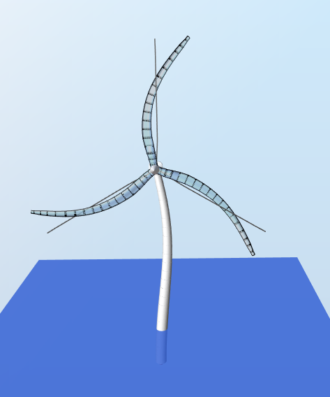
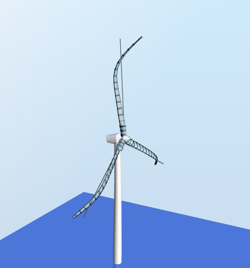
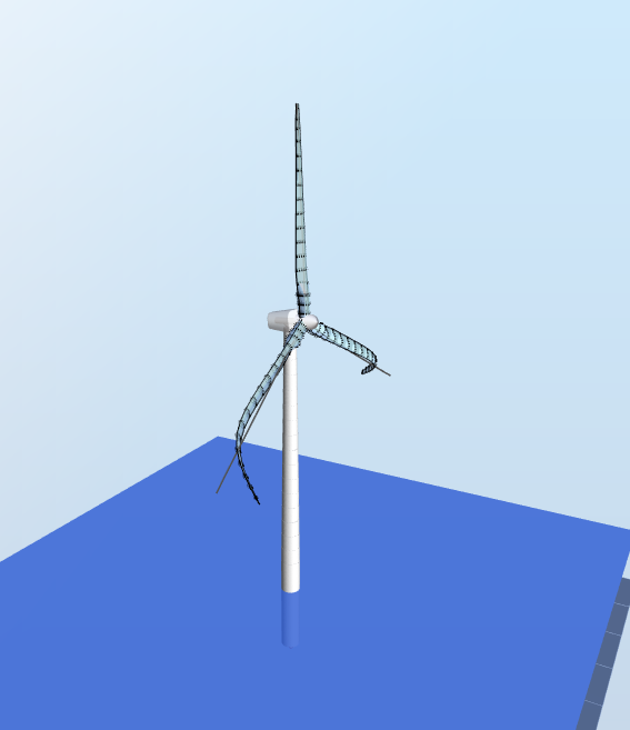
In the following sections, the different mode shapes are illustrated.
3.1 First Tower fore-aft
3.2 First Tower side-to-side
3.3 First drivetrain torsion
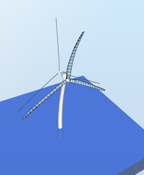
3.4 First Blade Collective Flap
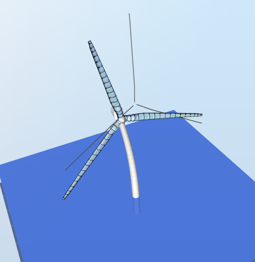
3.5 First Blade Asymmetric Flapwise Pitch
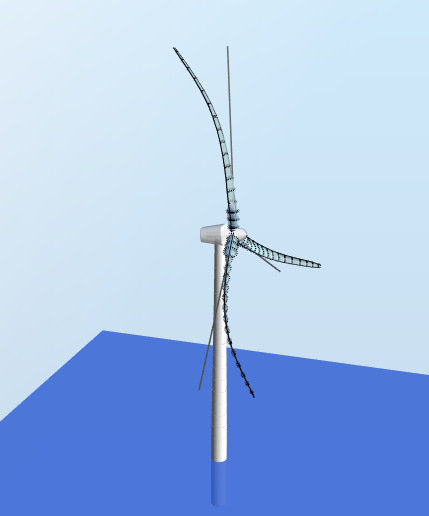
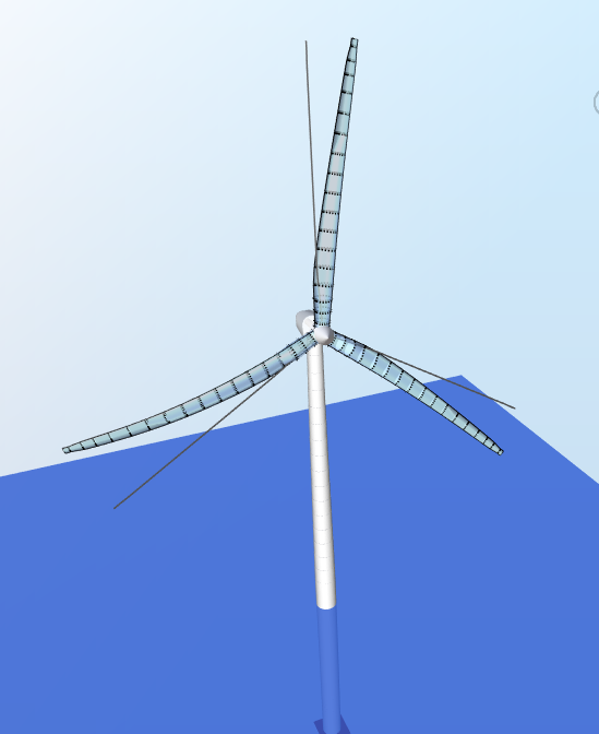
3.6 First Blade Asymmetric Flapwise Yaw
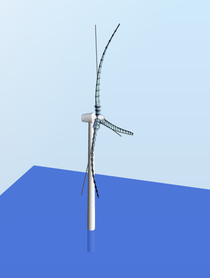
3.7 First Blade Asymmetric Edgewise Pitch
3.8 First Blade Asymmetric Edgewise Yaw
3.9 Second Tower Fore-Aft
3.10 Second Tower Side-to-Side
3.11 Second Blade Collective Flap

3.12 Second Blade Asymmetric Flapwise Pitch
3.13 Second Blade Asymmetric Flapwise Yaw
4 Results
The eigenfrequences of the model are solved and compared to those presented in the OC3 Phase I project. Note that the numbering of the eigenfrequencies in Ashes is from the lowest frequency to the highest, which is not the same as in the OC3 Phase I project. The table below summarises the numbering correspondance.
| Mode number in Ashes | Mode name | Mode number in OC3 Phase I |
| 1 | 1st Tower Side-to-Side | 2 |
| 2 | 1st Tower Fore-Aft | 1 |
| 3 | 1st Drivetrain torsion | 3 |
| 4 | 1st Blade Asymmetric Flapwise Yaw | 6 |
| 5 | 1st Blade Asymmetric Flapwise Pitch | 5 |
| 6 | 1st Blade Collective Flap | 4 |
| 7 | 1st Blade Asymmetric Edgewise Pitch | 7 |
| 8 | 1st Blade Asymmetric Edgewise Yaw | 8 |
| 9 | 2nd Blade Asymmetric Flapwise Yaw | 13 |
| 10 | 2nd Blade Asymmetric Flapwise Pitch | 12 |
| 11 | 2nd Blade Collective Flap | 11 |
| 12 | 2nd Tower Side-to-Side | 10 |
| 13 | 2nd Tower Fore-Aft | 9 |
Note that only a visual check is performed in that report. Once we have a set of results that are in agreement with the other participants, we use that set as a base case to compare the results produced by Ashes daily. If these results differ from more than 0.01% with the base, a failed test notification is raise. The report can be found on the following link: