DTU 10-MW steady state performance
In this document we compare results produced by Ashes with the DTU 10-MW twind turbine for constant uniform wind speeds ranging from 4 to 25 m.s
-1
.
1 Model
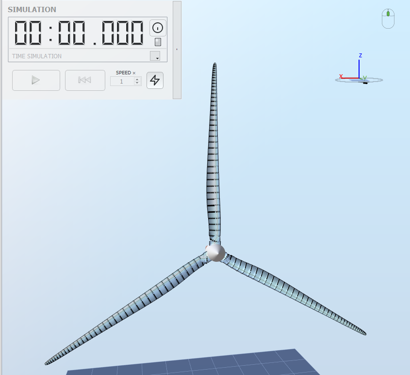
The model used for this benchmark corresponds to the RNA of the DTU 10-MW reference wind turbine (the tower is not considered). The document
Reference models
shows how to generate this model in Ashes.
The figure below illustrates the model:

2 Benchmarks
Constant uniform wind speeds ranging from 4 to 25 m.s
-1
are used as environmental conditions. Each wind speed corresponds to a load case. For each load case, 150 seconds are run and the value of the
Thrust, Aerodynamic power, Cp, Ct, Collective pitch angle
and
Rotor RPM
are extracted. All these outputs are part of the
Rotor sensor
. These results are benchmarked against tables 3.2a and 3.5 in
Bak et al. (2013)
.
3 Results
The report with the results can be downloaded here:
For each output in each load case, only the last 30 seconds of the time series are considered to ensure that transients are not taken into account. A test is considered passed if the results produced by Ashes are within 5% of the benchmark.
Note that there are some differences between the model in Ashes and the one presented in
Bak et al. (2013)
. This and some additional relevant information are listed below.
- In the model described in Bak et al. (2013) , the airfoil polars are interpolated within the blade, so that there are potentially as many polar sets as Blade aerodynamical station. This is not the case in Ashes.
- No information is provided as to what aerodynamic corrections were applied in the benchmark. The default conditions (i.e. those applied when opening a template) where used in Ashes. These include hub and tip loss and Glauert's correction (see BEM algorithm ). To obtain a good match at high TSRs (i.e. low wind speeds in this test), a Critical Glauert's value of 0.3 is applied
- The simulations in Ashes were performed with the Unsteady BEM method, except for the cases at 4 and 5 ms wind speeds, where the Steady BEM method is used. This is because the dynamic stall model was giving inaccurate results at those wind speeds (see section 5 Dynamic stall issue at low wind speeds in the DTU 10-MW document)