Morison test
This test ensures that the loads produced by the Morison equation in Ashes are correct.
1
Test description
This test uses a monopile in regular waves. The monopile is composed of two elements: one that does not experience any hydrodynamic loads and that is fixed and one that experiences hydrodynamic loads. To check that the loads are correctly calculated, the
Shear force
from the
Beam element sensor
of the fixed element and the total drag and inertia loads from the
Total hydro loads sensor
are checked. The monopile is infinitely stiff, and there are no other loads than the hydrodynamic loads. Therefore this shear force will be equal to the hydrodynamic loads. The following load cases are run:
-
H = 5 m L = 120 m
-
H = 5 m L = 120 m Cm = 2
-
H = 5 m L = 120 m Cd = 1
-
H = 5 m L = 120 m D = 4 m
-
H = 5 m T = 10 s
-
H = 5 m T = 10 s h = 200 m
-
H = 2 m T = 5 s
-
H = 2 m T = 5 s h = 10 m
2
Model
The model is illustrated in the figure below.
The default model for this test has a diameter
$$D = 6\text{ m}$$
and the element with hydrodynamic loads has a length
$$dz = 5\text{ m}$$
. The mass and drag coefficients are equal to
$$C_M = 1.63$$
and
$$C_D = 1.2$$
, respectively. The water depth is
$$h = 20\text{ m}$$
, and the element experiencing hydrodynamic loads extends from a vertical coordinate
$$z = -5\text{ m}$$
to the mean sea level at
$$z = 0$$
.
The acceleration due to gravity is
$$g = 9.80665\text{ m}\cdot\text{s}^{-2}$$
and the water density is
$$\rho = 1026.9\text{ kg}\cdot\text{m}^{-3}$$
.
3
Analytical solution
We only consider linear regular waves in these tests. These are defined by a wave length
$$L$$
and a wave height
$$H$$
. The wave number is defined as
$$k = 2\pi/L$$
. The wave frequency
$$\omega$$
can be obtained through the linear disperson relationship, such that
$$\omega^2 = gk\tanh(kh)$$
, and the wave period is equal to
$$T = 2\pi/\omega$$
.
The force at time
$$t$$
and height
$$z$$
is given by the Morison equation. Since we consider a fixed, infinitely stiff structure, the Morison equation given in
Wave loads
can be reduced to
$$F(z,t) = \frac{1}{2}\rho C_D D u(z,y)|u(z,t)|dz + \rho C_M\pi\frac{D^2}{4}a(z,t) dz$$
where
-
$$u(z,t)$$
is the wave particle velocity
-
$$a(z,t)$$
is the wave particle acceleration
The particle velocity is given by
$$u(z,t) = \omega\frac{H}{2}\frac{\cosh\left(k(z+h)\right)}{\sinh(kh)}\sin(\omega t)$$
The particle acceleration is given by
$$a(z,t) = \omega^2\frac{H}{2}\frac{\cosh\left(k(z+h)\right)}{\sinh(kh)}\cos(\omega t)$$
Note:
in Ashes, the hydrodynamic load is computed at the midpoint of the corresponding element. For this test, since the element goes from
$$z = -5\text{ m}$$
to the mean sea level, the load will be compute using the kinematics at
$$z = -2.5\text{ m}$$
For each load case, the parameters that are changed with respect to the default model are given in the title. For example, the first load case is called
H = 5 m L = 120 m
, which means that this load case uses the default values with a wave height
$$H = 5\text{ m}$$
and a wavelength
$$L = 120\text{ m}$$
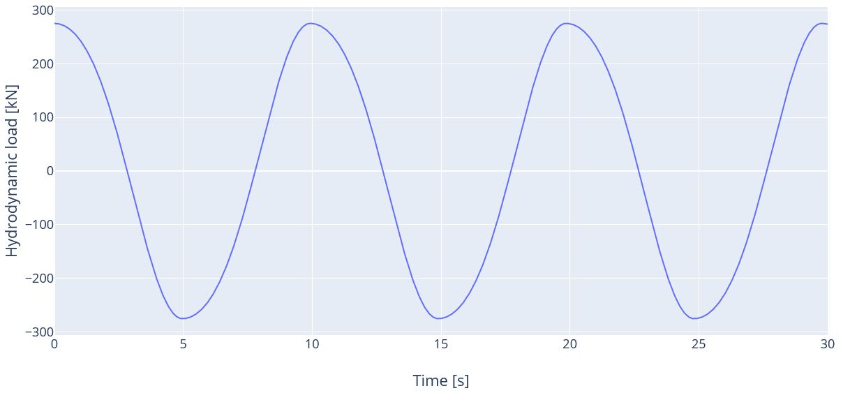
. For this test, the expected total hydrodynamic load (i.e. drag + inertia loads) is shown in the figure below:
4
Results
A simulation of 30 seconds is run for each load case. The results are considered passed if the results from Ashes are within 2% of the analytical solution.
The report for this test can be found on the following link:

