Changing the reference wind speed will change the Reynolds number at each blade element. This will influence the results if the airfoils used in the blades have Reynolds dependent polars. In that case, the Reynolds numbre is calculated for each blade element and the lift and drag coefficients are interpolated from the polars with the closest reynolds numbers.
If the airfoils are defined by only one polar, as is the case for the NREL 5 MW blade provided by default, no interpolation is possible, and this polar is used for all computations. In that case, changing the reference wind speed will not change the Cp and Ct curves.
Rotor characteristics
Ashes gives the possibility to obtain the power coefficient (Cp) and thrust coefficient (Ct) over tip speed ratio (TSR) curves. This video shows how to obtaine them for the default onshore wind turbine:
https://www.youtube.com/watch?v=E83Q4I0FXvo
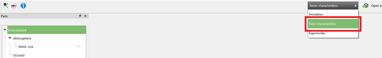
This will open the
Rotor characteristic window, which is illustrated below:
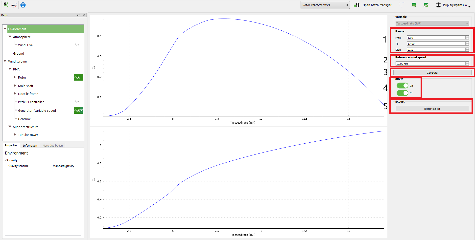
- Range: enables you to specify the start and end TSR and the TSR step
- Reference wind speed: in ordre to establish the Cp and Ct curves, Ashes will carry out steady BEM simulations with a constant reference wind speed and varying rotational speed to vary the TSR. This parameters sets the reference wind speed.
- Compute button: when pressing this button, the comutations will start. A pop-up window shows the progress of the computation.
- Cp and Ct switches: this enables you to select which curves to display
- Export button: when pressing this button, the results are exported as a text file composed of 3 columns containing TSR, Cp and Ct