Soil stiffness
Soil stifness (both translational and rotational) can be modeled when part of a support structure is below the ground. The parameter
Soil stiffness of a
Support structure (such as a
Monopile or a
Truss tower) defines the load that will be applied to a node that is under the ground.
The load that is applied to a node is equal to
$$F(t)=k_s\cdot\eta(t)\cdot (L_u/2+L_d/2)$$
where
-
$$k_s$$is the soil stiffness, in$$\text{N}\cdot \text{m}^{-2}$$for soil translational stiffness and in$$\text{N}\cdot\text{rad}^{-1}$$for soil rotational stiffness
-
$$\eta(t)$$is the displacement of the node, in$$\text{m}$$for soil translational stiffness and in$$\text{rad}$$for soil rotational stiffness
-
$$L_u$$and$$L_d$$are the lengths of the elements above and below the node if they are still below the ground. If the node is at the seabed for example, only the element below the node will contribute to this equation
In the code, the soil stiffness is modeled as a linear spring on the node. The stiffness of the spring can thus be computed as
$$k = k_s\cdot(L_u/2+L_d/2)$$
This can be viewed by right-clicking the spring in the GUI, as shown below:
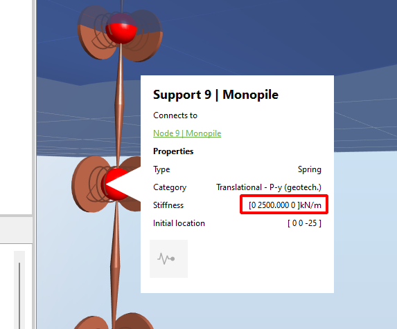
This was obtained by using the default Offshore template and setting the
Vertical offset of the support structure to -20. In this configuration, the soil (linear) stiffness is by default
$$k_s=500000\text{ N}\cdot \text{m}^{-2}$$
and all elements have the same length
$$L=5\text{ m}$$
The soil stiffness is thus
$$k=k_s\cdot(L/2 + L/2)=500000\cdot5=2500\text{ kN}\cdot\text{m}^{-1}$$
as shown in the figure.
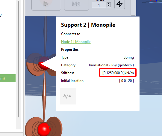
Note that for the node at the seabed, as explained before, only the element below the node will contribute with soil stiffness. Therefore the spring stiffness applied to the seabed node will be half of that applied to the node from the previous example, as shown in the figure below: