Loads on node sensor
You can add a sensor that gives you all the loads being applied on a node, called
Loads on node
sensor. Note that in Ashes, all loads are given a unique number for the duration of the simulation. This number can be found by going to the
FEM diagnistics tab when opening the info button in the top ribbon (see
Simulation window). In the
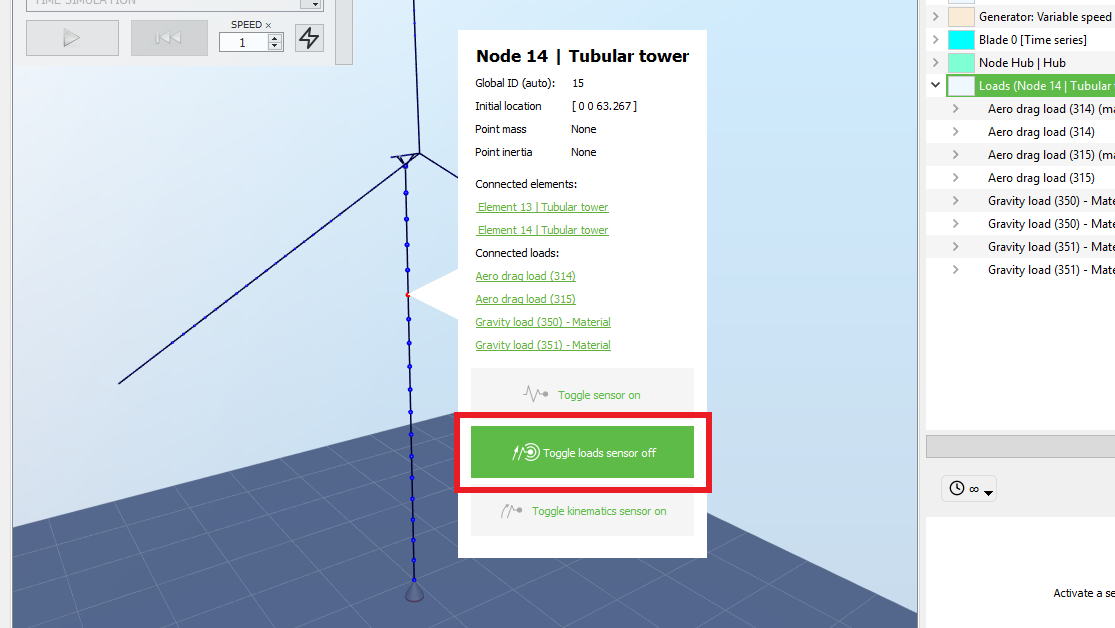
Loads on node sensor, this number will appear in parenthesis next to each load.
You can right click on the node and toggle the sensor on by clicking the sensor button, as shown on the picture below. Note that it is easier to visualize the nodes in wireframe mode by clicking the
Wireframe button in the top ribbon of the
Simulation window.
Only the loads that are applicable will be shown in the sensor. For example, if no aerodynamic coefficients are specified for a given cross section, no aerodynamic loads will be applied on the nodes defining elements with this cross section. You can see how to specify coefficients in the
Cross section keyword of the
Keywords section
The
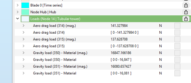
Loads on node sensor provides the following fields. Note that for each load, the magnitude is given (with the text "mag." in parenthesis) and then the 3 components of the vector are listed.
The components of the vectors are given in the global coordinate system (see
Coordinate systems)
| Field | Unit | Description |
| Aero drag load | N | Aerodynamic load corresponding to the drag term of the Morison equation |
| Gravity load - Material | N | Weight of the material composing the element connected to the node |
| Hydro drag load | N | Hydrodynamic load corresponding to the drag term of the Morison equation |
| Wave load inertia | N | Hydrodynamic load corresponding to the inertia term of the Morison equation due to the wave particle acceleration |
| Added mass (perp.) eq. load | N | Hydrodynamic load in a direction perpendicular to the element, equivalent to the added mass term of the Morison equation (therefore due to the motion of the structure) |
| Buoyancy load | N | Buoyancy of the element |
| Gravity load, filling | N | Weight of the material filling the hollow cross section composing the element, typically water filling the monopile. Equal to 0 if no filling is specified |
| Gravity load, growth | N | Weight of the marine growth on the element. Equal to 0 if no marine growth is specified |
| Seabed friction | N | Load produced by the friction of the seabed on the element (see the Mooring system part for more info) |
| Seabed stiffness | N | Load produced by the stiffness of the seabed on the element (see the Mooring system part for more info) |