Create a custom rated power turbine
This section is a step-by-step guide on how to create a simple turbine with a custom rated power. Ashes provides default blades for the
NREL 5 MW and the
DTU 10 MW wind turbines, which characteristics can be found on the
Reference models.
In this section we will create an 8
MW
turbine, taking as a starting point the reference 5 MW turbine. The input to this process is the rated wind speed and an estimation of the maximum power coefficient of the rotor.
Note: following this guide, you will generate a simple model of a custom rated power wind turbine. A number of simplifications are taken during the process, but the turbines thus obtained generally produce a good estimate of the aerodynamic loads. To the best of our knowledge, this is generally sufficient for preliminary analyses of support structures.
1 Create an 8 MW blade
In order to create the blade for our 8 MW turbine, we will upscale the NREL 5 MW blade. The first step is to establish the length that the blades will have. The rated power of a rotor is given by
$$P_r = \frac{1}{2}\rho V_r^3AC_{Pmax}$$
where
-
$$\rho$$is the density of the air
-
$$V_r$$is the rated wind speed
-
$$A$$is the projected area of the rotor. In this guide, we assume$$A = \pi R^2$$where$$R$$is the rotor radius and is equal to the sum of the hub radius and the blade length. This implies that we neglect the cone and the tilt angles.
-
$$C_{Pmax}$$is the maximum power coefficient of the rotor (see CP - Power coefficient)
Inserting the rotor radius and reorganizing this equation yields
$$R = \sqrt{\frac{2P_r}{\rho \pi V_r^3C_{Pmax}}}$$
For this turbine, we assume that the rated wind speed is
$$V_r = 11.4 m\cdot s^{-1}$$
and that
$$C_{Pmax} = 50\%$$
. This initial guess will be adjusted later. With a rated power
$$P_r = 8 e^6 W$$
and a density of the air
$$\rho = 1.225 kg\cdot m^{-3}$$
we obtain a rotor radius
$$74.9 m$$
. To find the blade length, we have to substract the hub radius to the rotor radius. For the NREL 5 MW turbine, the hub radius is equal to 2.4% of the blade length. If we keep this ratio on our turbine, the blade length will be
$$B_L = 73.1 m$$
and the hub radius is
$$R_H = 1.8 m$$
.
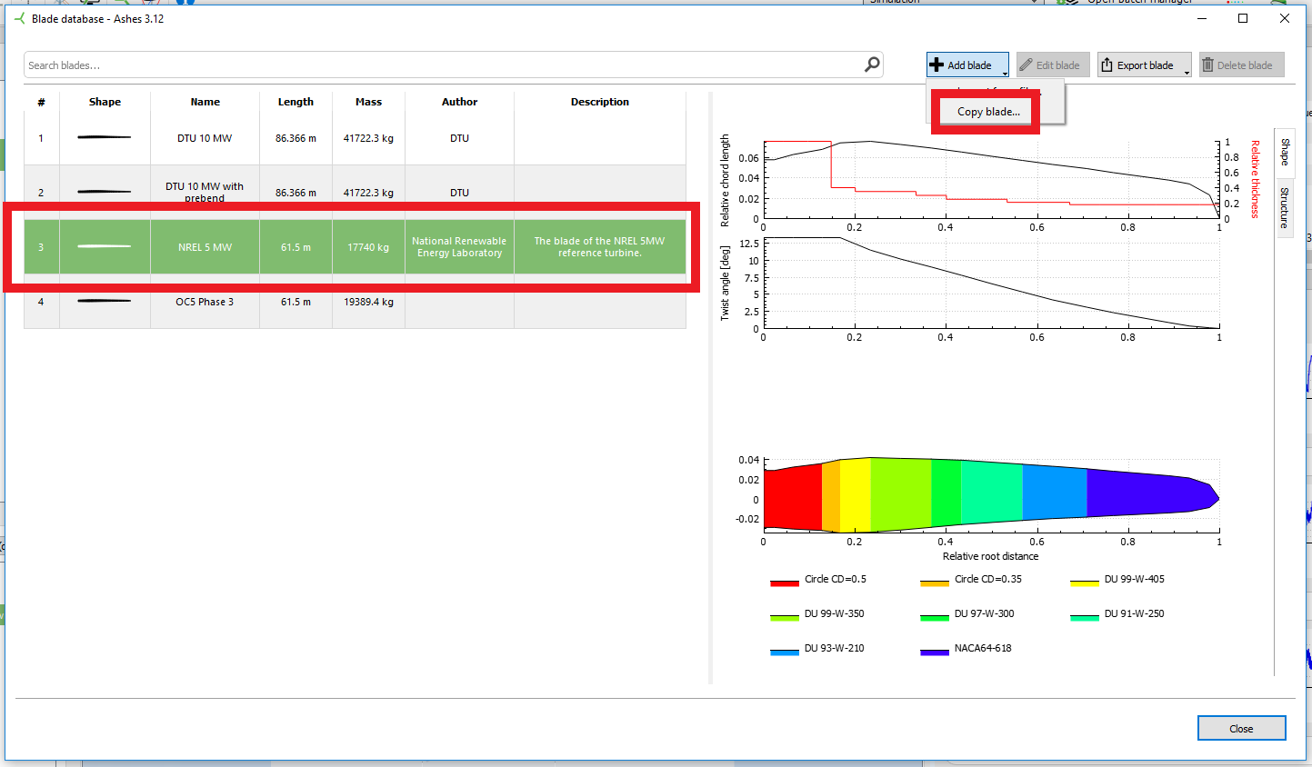
Now that the blade length is defined, we will copy the 5 MW blade and increase its length to match ours. Go to the
Blade database, select the
NREL 5 MW blade, click
Add a blade and select
Copy blade, as shown in the picture below:
This will open the following dialog:
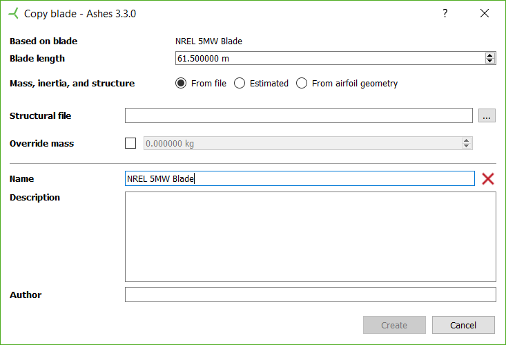
In this dialog, enter the length of our blade in the
Blade length field. For the
Mass, inertia and structure, we recommend using the
Estimated option, unless you have a definition of the structure of the blade. The three options are explained more in detail in the
Blade database section.
Enter a name for the blade, click
Create and your new 8 MW blade will automatically be saved into the blade database. You can now select your blade in the
Rotor part.
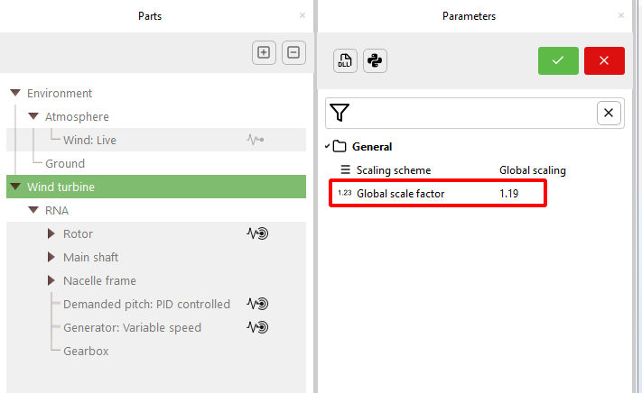
2 Adjust the size of the turbine
Now the blade is created, but the rest of the model (support structure, nacelle, etc) still corresponds to the NREL 5 MW. In order to scale up the rest of the turbine, it is possible to use the Scaling scheme parameter in the Wind turbine part and set it to Global scaling. The value of the global scaling should be the ratio of the length of your blade over the NREL 5 MW blade, so in our case
$$73.1/61.5=1.19$$
Notes:
- The template is based on the NREL 5 MW turbine, so even if you are using other blades (such as the DTU 10 MW) as the base for creating your blade, you will have to use the length of the NREL 5 MW blade when calculating the global scaling ratio
- The distances are multiplied by the global scaling, the masses are multiplied by the global scaling cubed
- The generator parameters, gearbox, mooring lines and any imported support section are not affected by global scaling
The figure below illustraates where the
Global scaling parameter is changed:
Note: when
Global scaling is selected in the Scaling scheme parameters, the parameters' values shown in the parts pane are
NOT multiplied by the parameter, but their value in the model is. For example, after applying the 1.19 global scaling, if you go to the
Hub radius parameter, you will see that the value shown is still 1.5 m. However, if you go to the information tab, the value of the hub radius is 1.78 m, which is the effective hub radius used in the model. If you want the value shown in the properties tab to match that of the info tab and the model, set the
Scaling scheme back to none. The global scaling value that you applied now defines the model, and the model assumes there is no scaling anymore.
3 Generator
Now the whole model has the correct dimensions, but the controller is still tuned to produce 5 MW. In order to obtain a relevant controller, the first step is to go to the Generator:
Variable speed part and change the
Rated electrical power parameter to 8 MW.
With this change, the turbine will be able to generate 8 MW at high wind speeds, but it will not necessarily operate at its maximum C
P
under rated or at rated wind speed. To explain why, we will analyze the situation at rated wind speed, and remind that the maximum C
P
is obtained for a given Tip Speed Ratio (TSR), named
Optimal TSR
and hereafter noted
$$TSR_{opt}$$
. The TSR is defined as the ratio between the speed of the tip of the blade and the wind speed, and can be obtained with the following formula:
$$TSR = \frac{tip speed}{wind speed} = \frac{\Omega\cdot\frac{2\pi}{60}R}{V}$$
where
$$\Omega$$
is the rotational speed of the rotor in revolutions per minute (RPM). At rated conditions, the turbine operates at the optimal TSR and the following equation holds:
$$TSR_{opt}=TSR_r = \frac{\pi \Omega_r\cdot R}{30V_r}$$
Note: for wind speeds lower than the rated wind speed, the turbine is also operating at the optimal TSR. However, for determining the rated rotational speed, it is necessary to place ourselves at rated conditions.
In the present case, the rotor radius and the rated wind speed are given, so if we want to operate at the optimal TSR we need to select the right rotational speed. This is done as follows:
3.1 Establish the optimal TSR
Go to the
Rotor characteristics mode and compute the C
P
curve by pressing the
Compute button. This will produce the curve shown in the figure below, from which the optimal TSR and the maximum C
P
can be established:
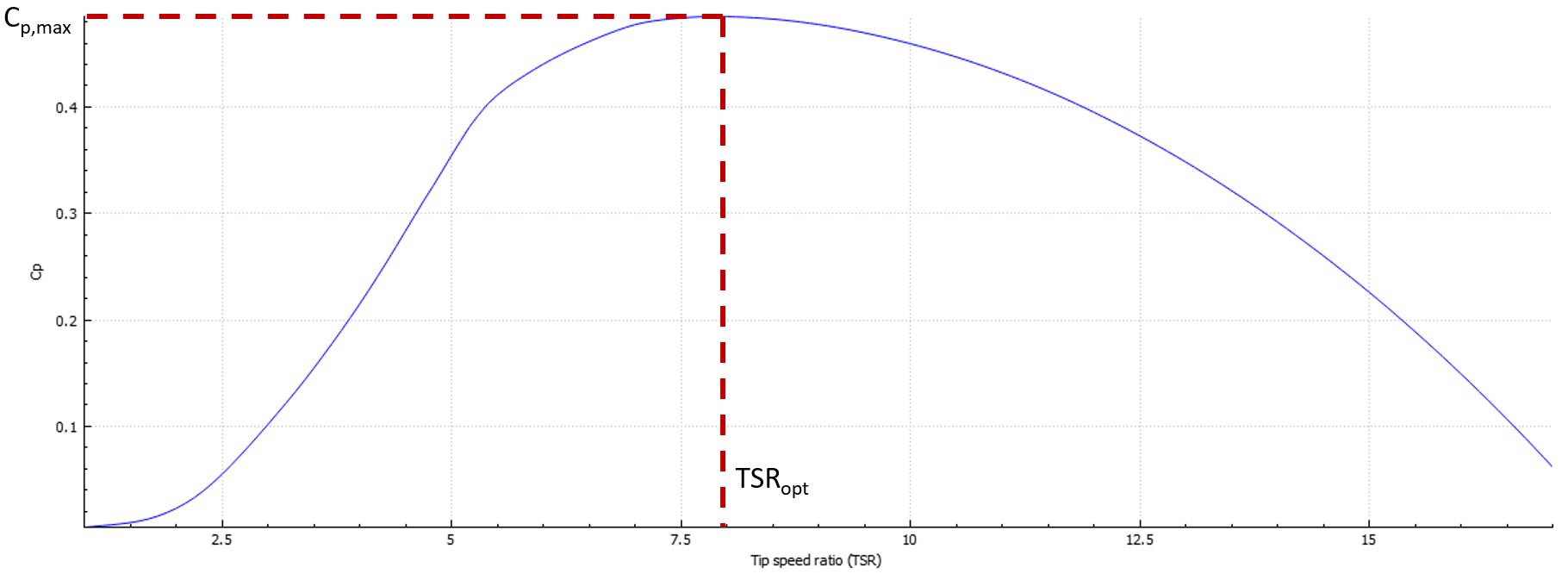
In this example, the optimal TSR is 7.9 and the maximum C
P
is 48.5%
Note: it is also possible to pick a different TSR than the optimal TSR. This can be for structural reasons, or to reduce noise for example.
To get an accurate estimatione of those values, it is possible to change the range of the computation of the C
P
curve.
3.2 Find the actual rated speed
Go to the
Rotor part and in the
Advanced section, change the
Target C
P to 48.5%. If you now go to the
Information tab, you can find the
Required rated speed, which has a value of 11.75 m.s
-1. This is the wind speed necessary to produce 8 MW with our current rotor and maximum C
P.
This is different than the value that we initially input into the equations, because of these two reasons:
-
Our initial guess of maximum C
P
was slightly higher than the actual maximum C
P
of the rotor
- The actual rotor has a cone and a tilt angle, which reduce the effective rotor area facing the wind
If the difference between the required rated wind speed and the actual rated wind speed is too large, we recommend iterating on this process with the new maximum CP and including the cone and tilt angles in the initial calculation.
3.3 Establish the rated RPM
Now that we have the rated wind speed, we can reorganize the TSR equation to calculate the rated rotational speed:
$$RPM_r=\frac{30TSR_{opt}\cdot V_r}{\pi R}$$
With a wind speed of 11.75 m.s
-1, an optimal TSR of 7.9 and a rotor radius of 74.9 m, this gives a rated rotational speed of 11.8 RPM. Note this value was obtained with aerodynamic considerations only. If this value is too high and would for example induce a too high tip speed, you can change it now.
Note: to be accurate, the radius of the projected area should be used in this equation, i.e. the cone and tilt angle should be taken into consideration. The radius of the projected are can be found in the information pane of the rotor.
3.4 Adjust the generator or the gearbox
We have now established the rated rotational speed of the rotor. In practice, this rotational speed cannot directly be modified, as it is determined by the rotational speed of the generator and the gearbox through the following equation:
$$\Omega\cdot G = \Omega_{gen}$$
where
$$G$$
is the gearbox ratio and
$$\Omega_{gen}$$
is the generator rotational speed. Therefore, to ensure that the rated rotational speed of the rotor is correct, we must either adjust the rated rotational speed of the generator or the gearbox ratio. This can easily be done by changing the
Target rated rpm in the
Advanced section of the
Rotor properties to 11.8 RPM, then going to the
Information
pane and checking the suggested gearbox ratio or rated generator rotational speed, as shown in the image below: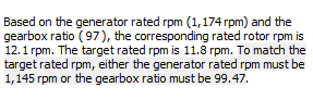
In the present case, we chose to change the rated rotational speed of the generator to 1 145, in the
Rated RPM parameter of the Generator
Variable speed part.
Note: it is also possible to use a combination of rated generator rotational speed and gearbox ratio that will produce the correct rotor rotational speed
4 Pitch controller
The last step in the process is to tune the pitch controller. The default pitch controller in Ashes is a simple
PI controller, for which the
proportional gain
$$K_P$$
and the
integral gain
$$K_I$$
can be tuned in the
Demanded pitch part.
Note: it is also possible to use the derivative term, in which case the controller becomes a PID controller.
The difficulty in tuning the gains lies in the fact that the sensitivity of the aerodynamic power to pitch varies depending on the pitch angle. In other words, a 1 degree pitch increment will produce different variations of the aerodynamic power when the pitch angle is 0 or when it is 10 degrees. This is taken care of by the
Gain scheduling parameter in the
Demanded pitch part. Enabling gain scheduling will change the gains depending on the pitch angle.
The details of this controller can be found in
Jonkman et al. (2009o).
Here we propose a heuristic method that to find the PI gains and the Gain scheduling parameter, following these steps:
4.1 Find the gains at 0 pitch
The first stage in this procedure is to find the proportional and integral gains at 0 pitch. For this, we place ourselves just below the rated wind speed, in our case at 11 m/s, and we disable gain scheduling by ticking off the correponding box.
To find the gains at 0 pitch, we apply the
Ziegler-Nichols
method (see
Wikipedia). For this, we set the integral gain to
$$K_I = 0$$
, and the proportional gain to a small value, for example
$$K_P=0.002 s$$
. We then increase the wind to 12 m/s and see how the pitch angle evolves. The aim of this first stage is to increase the value of the proportional gain gradually until the pitch angle starts producing divergent oscillations. In our case, the output is shown in the figure below.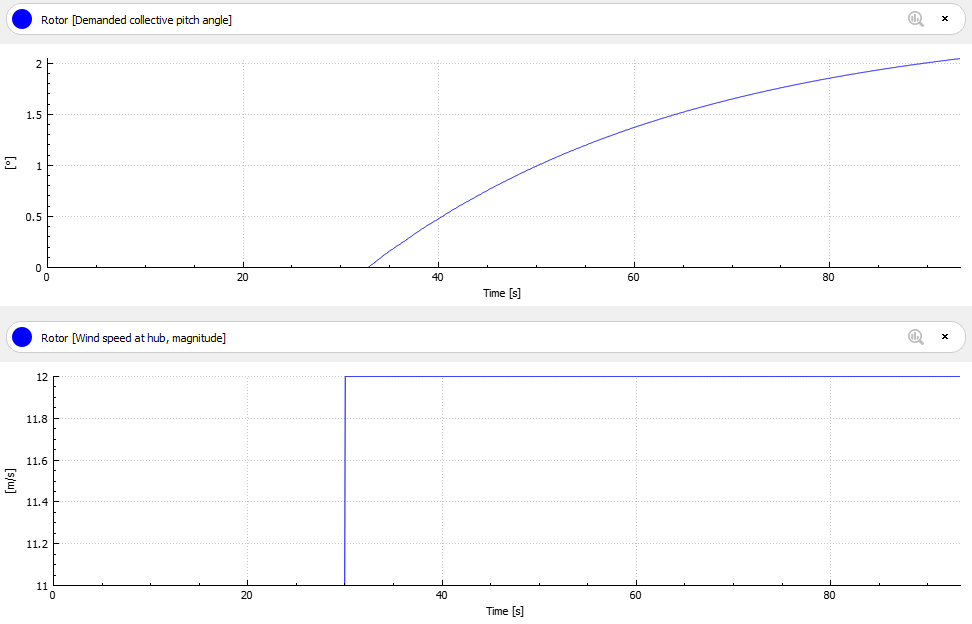
With this value of
$$K_P$$
, the pitch angle does not exhibit any oscillations, so we can increase the value to for example
$$K_P = 0.02 s$$
. The output is shown in the image below: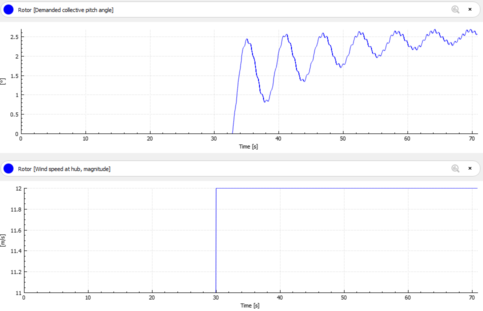
The pitch angle output now shows some oscillations, but is convergent, so we can keep increasing the proportional gain to for example
$$K_P=0.04 s$$
. The pitch angle output is shown below: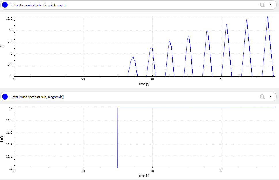
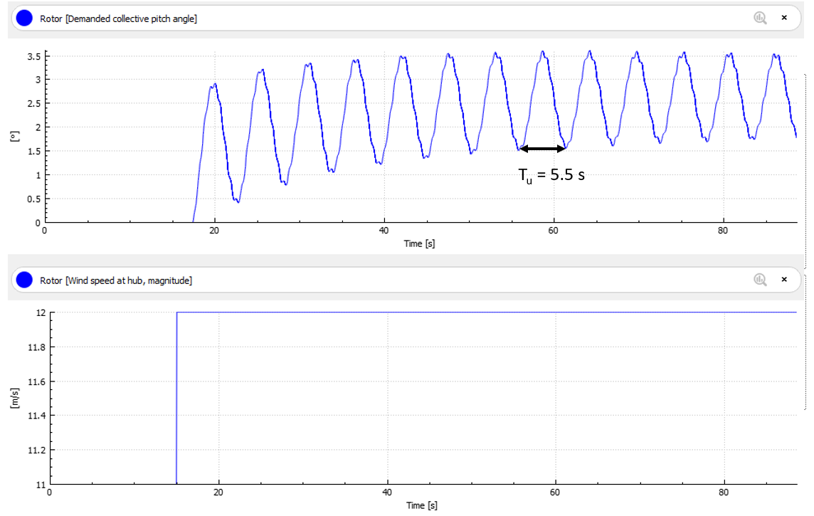
Now the pitch angle is clearly divergent, so we need to reduce the value of the proportional gain. By going back and forth with
$$K_P$$
, it seems like oscillations will start to become divergent from
$$K_P=0.023s$$
, as shown in the image below. We then take this as the value of the ultimate gain
$$K_u = 0.0023s$$
. The ultimate oscillation period is the period of the oscillations of this output, in our case
$$T_u = 5.5 s$$
.
The Ziegler-Nichols method suggests the following values for the proportional and integral gains :
$$K_P = 0.45K_U=0.01035s$$
$$K_I=0.54\frac{K_U}{T_U}=0.002258$$
When accurate values are sought, it is recommended to use the
Batch manager to automatize the procedure.
4.2 Find the Gain scheduling value
The gains found with this method provide good results at 0 pitch, when increasing the wind speed from 11m/s to 12 m/s. However, for the reason explained above, they will not necessarily produce good results at higher wind speeds. In our case, changing the speed from for example 23 to 24 m/s will produce oscillations in the pitch angle which will take some time to decay. Depending on the purpose of the controller, this could be fine, but if it is not we nee to apply
Gain scheduling. Gain scheduling will decrease the gains for increasing pitch angle following the equation
$$K_P(\theta) = K_P(0)\frac{1}{1+\theta/\theta_k}$$
$$K_I(\theta)=K_I(0)\frac{1}{1+\theta/\theta_k}$$
where
-
$$\theta$$is the pitch angle
-
$$\theta_k$$is the Pitch angle parameter of the Demanded pitch part
More information about gain scheduling can be found in
Jonkman et al. (2009o).
To find an adequate value for the
Pitch angle parameter, the suggested method is simply to run several simulations with a
Stepwise wind with different values and visually check that the pitch angle behaves as expected at all wind speeds. In our case, we run a stepwise wind going from 11 m/s to 25 m/s (so a range from just below rated to cut-off).
By visual inspection of the results, we pick a value for which all output behave as required. For the pitch angle for example, this implies that the final value is reached relatively fast without too many oscillations. The image below shows the pitch angle obtained for our turbine for the values of the
Pitch angle parameter
in the legend ('-' means no gain scheduling). The image to the right is a zoom of the results.
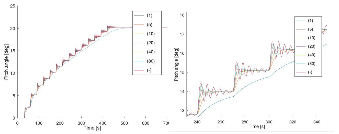
Based on this figure, we select a value for the
Pitch angle parameter
of 10 derees.
4.3 Summary of the procedure for tuning the PI controller
- set all gains to 0 and remove gain scheduling
- set the wind speed just under the rated wind speed, and apply a step so that the wind increases just above the rated wind speed
- gradually i ncrease the proportional gain until the pitch exhibits unstable oscillations: this gives the ultiamte gain and period
- from the ultimate gain and period, compute the proportional and integral gains following the Ziegler-Nichols method
- turn back on gain scheduling
- run a sensitivity study on the Pitch angle parameter
- by means of visual inspection, keep the value that provides the best output