Aerodynamical reference point
The
Aerodynamical reference point
is a characteristics of a given airfoil..
The aerodynamical reference point is defined for each airfoil in the
Airfoil database
, by the coordinates of the
relative reference point
. These coordinates are given as a
relative
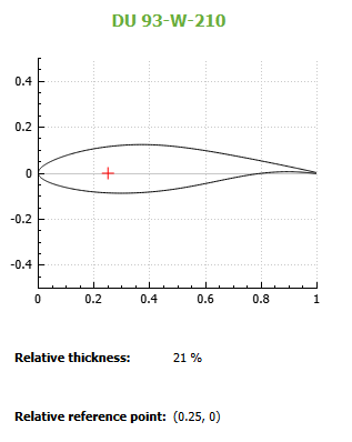
value since they are normalized with the chord length. The figure below illustrates the definition of the reference point for the DU 93-W-210 airfoil.

In this figure, the aerodynamical reference point is marked in red. Since its coordinates are (0.25, 0), the point lies on the chordline, at a quarter of the chord length from the leading edge.
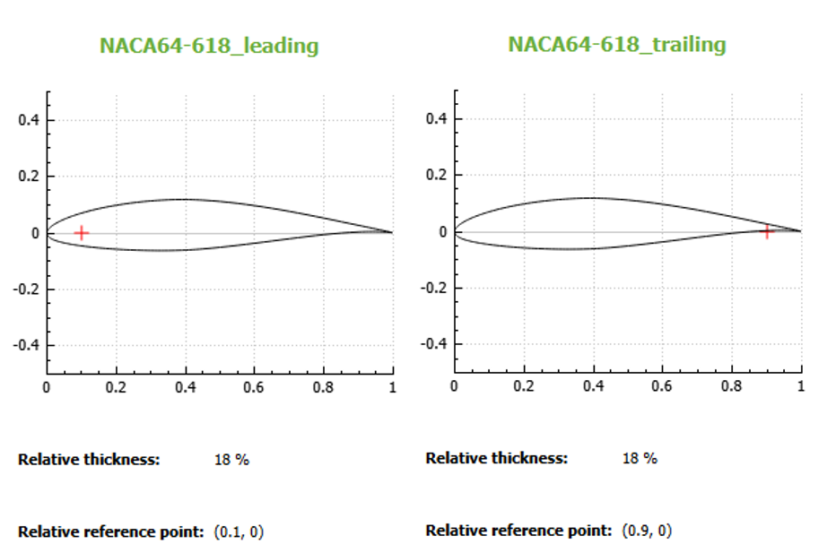
A horizontal coordinate of 0 sets the reference point at the leading edge, a coordinate of one sets on on the trailing edge. The figure below on the left and the right illustrate the reference point for coordinates (0.1, 0) and (0.9, 0), respectively.

When importing a new airfoil, the reference point will be defined in the
Airfoil geometry file
.
Note:
currently, only reference points located on the chordline are allowed in Ashes. This means that the second coordinate will always be 0
1 Use of the aerodynamical reference point
The aerodynamcal reference point is defined when generating the polars (for example with software like XFoil) and is the point around which the
moment coefficients
(Cm) are given. This means that the aerodynamical reference point can be chosen arbitrarily, and its position should be taken into account when computing the moment coefficients.
It also means that for an airfoil that has a polar with its moment coefficients defined around a certain aerodynamical reference point, it is possible to produce a new polar with the moment coefficients defined around a different aerodynamical reference point.
Note:
in Ashes, the
aerodynamical reference point
is used when applying moments due to lift and drag. The offset bewteen the aerodynamical reference point and the shear center will be used to compute the pitching moment applied to the blade element.
The aerodynamical reference point should not be confused with the
Aerodynamic center
, which is the point of an airfoil geometry at which the moment coefficient does not vary with the angle of attack (see
Wikipedia
).
To add to the confusion, a physical property of thin airfiols at low wind speeds is that the aerodynamic center is located at 25% along the chordlength from the leading edge (this point is also called the quarter point ). Probably because of that, it is common to set the aerodynamical reference point at 25% along the chordline as well (but since it is an arbitrary value, that is not always the case, and aerodynamical reference points for circular cross sections for example are generally set at center of the circle). However, the moment coefficient around the quarter point does generally depend on the angle of attack, because the assumptions of thin airfoils and low wind speeds generally do not appy to wind turbines.
To add to the confusion, a physical property of thin airfiols at low wind speeds is that the aerodynamic center is located at 25% along the chordlength from the leading edge (this point is also called the quarter point ). Probably because of that, it is common to set the aerodynamical reference point at 25% along the chordline as well (but since it is an arbitrary value, that is not always the case, and aerodynamical reference points for circular cross sections for example are generally set at center of the circle). However, the moment coefficient around the quarter point does generally depend on the angle of attack, because the assumptions of thin airfoils and low wind speeds generally do not appy to wind turbines.