-
If the wind has a component parallel to the axis of the tower, that component is ignored. This is the case for example for the vertical component of
turbulent wind
when computing the tower shadow effect for vertical towers.
-
To calculate the tower shadow at a given blade station, the local incoming wind velocity
at the location
of the blade station, is used (rather than the mean wind speed or the wind speed at hub high)
Powles tower shadow model
To simulate the tower shadow for a
downwind wind turbine, the wind flow around the tower can be modeled using the
Powles tower shadow model (see
Powles (1983) and )
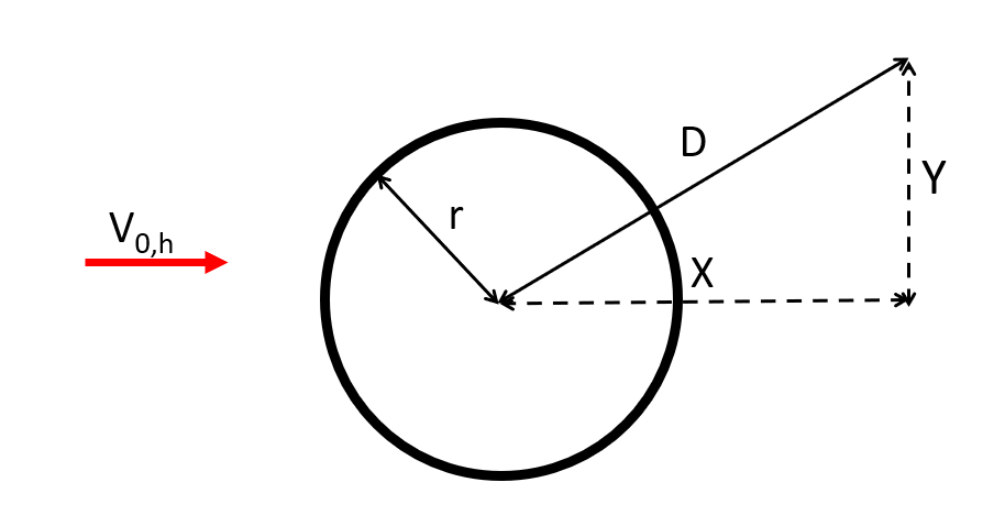
The equations are described for the following case: consider a
Blade aerodynamical station at a distance
$$D$$
of the tower. The distance to the tower in the incoming wind direction is
$$X$$
and the distance in the perpendicular direction (in the horizontal plane) is
$$Y$$
, such that
$$D = \sqrt{X^2+Y^2}$$
The tower has a radius
$$r$$
.
Note
$$V_{0,h}$$
.
The figure below illustrates this case:
Note: A tower shadow is not necessarily produced by a tubular tower. When using
truss towers, a tower shadow can be calculated based on a user-defined radius (see
shadow radius
parameter in the
Aerodynamics tab).
The modified horizontal wind speed is computed as
$$V_{n,h} = V_{0,h}-u_{wake}\cdot V_{0,h}$$
The term
$$u_{wake}$$
is called the
non-dimensional wake deficit, and is computed as
$$u_{wake}=\left\{\begin{array}{ll}C_D\cdot\cos^2\left(\frac{\pi y}{2\sqrt{d}}\right)\cdot \frac{1}{\sqrt{d}}&\text{for }|y|<\sqrt{d}\\ 0&\text{for }|y|>\sqrt{d}\end{array}\right.$$
where
-
$$C_D$$is the drag coefficient of the tower set by the user
-
$$d=D/r$$
-
$$y=Y/r$$
The fact that the wake deficit is only non-zero for
$$|y|<\sqrt{d}$$
implies that the tower wake grows in width as the distance from the tower in the sirection of the incoming wind increases. This is illustrated in the figure below: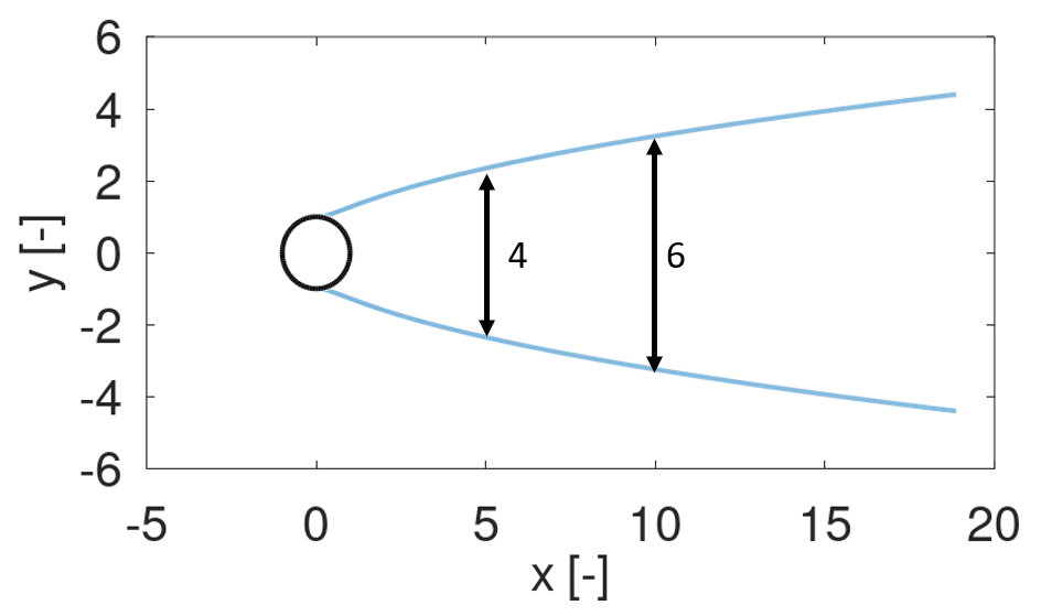
As an example, the wake 5 radii downstream from the tower will have a width of approximately 4 radii, and the wake 10 radii from the tower will have a width of 6 radii.
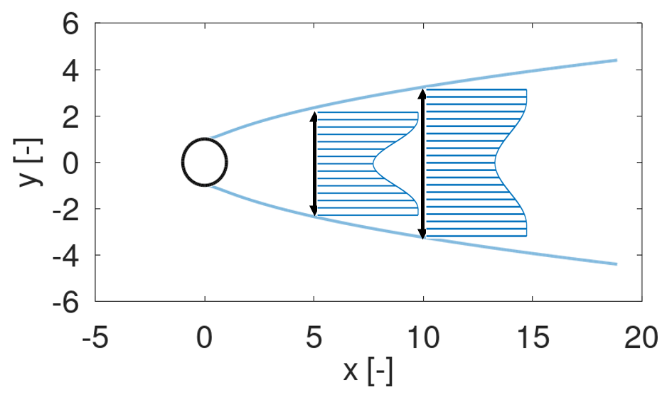
It can also be seen from the wake deficit equation that the strength of the wake decreases when moving further away from the tower. This is illustrated by the figure below, which shows that the wind speed behind the tower decreases less at 10 radii than at 5 radii.
1 Several parts of the structure
As described in
Tower shadow models, the shadow is cast by every straight run of elements with a circular cross section in the support section, and a rotor is shadowed by all of them - on a multi-rotor turbine by the mast and the arms alike. Each run is treated in the plane perpendicular to its own axis, so runs that are inclined or horizontal are handled like a vertical tower, and the wake deficits of the individual runs are added.
Note: the wake model is not defined inside the tower itself, which a blade station can reach when a rotor sweeps around the arm it is mounted on. Such a station is treated as lying on the surface of the run (
$$d$$
capped at 1), which is the closest the model comes to describing it.