Rotor sensor
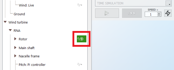
The rotor sensor can be added by toggling on the
Sensor button in the
Rotor part shown in the following picture:
For multi-rotor wind turbines, a sensor is available for each rotor
The
Rotor sensor provides the following fields:
| Field | Unit | Description |
| Power (aero) | W | aerodynamic power, i.e. the power exerted by the air on the blades |
| Torque (aero) | Nm | aerodynamic torque, i.e. the moment around the main shaft axis resulting from the aerodynamic forces on the blades |
| Thrust (aero) | N | total aerodynamic force on the rotor in the main shaft direction |
| RPM | rpm | revolutions per minute of the rotor, number of revolutions the turbine does in one minute. Also called Rotational speed or Rotational velocity |
| TSR | - | Tip speed ratio, ratio of the velocity of the tip of a blade over the wind speed magnitude at the hub |
| Representative demanded pitch angle | deg | Representative collective pitch angle demanded across the blades of the rotor. The pitch angle used is the demanded pitch angle for blade 1. |
| Demanded pitch angle, blade 1 | deg | Pitch angle demanded by the controller for blade 1. Only relevant when individual pitch control (IPC) is active; otherwise the collective demanded pitch applies to all blades. |
| Demanded pitch angle, blade 2 | deg | Pitch angle demanded by the controller for blade 2. Only relevant when individual pitch control (IPC) is active; otherwise the collective demanded pitch applies to all blades. |
| Demanded pitch angle, blade 3 | deg | Pitch angle demanded by the controller for blade 3. Only relevant when individual pitch control (IPC) is active; otherwise the collective demanded pitch applies to all blades. |
| Power coef. (CP) | % | Ratio of the aerodynamic power over the total available power in the wind (see CP - Power coefficient) |
| Thrust coef. (CT) | % | Ratio of the thrust force over the dynamic force in the wind |
| Torque coef. (CQ) | % | Ratio of the aerodynamic torque over the reference torque from the wind |
| Tip speed | m.s-1 | velocity of the tip of the blades. Calculated based on the RPM and the blade length |
| Azimuth angle | deg | angular position of the rotor. An azimuth angle of 0 means that the blade 0 is pointing upwards |
| Rotation per timestep | deg | degrees the rotor has rotated in one time step. The time step can be changed in the Analysis parameters |
| Wind speed at hub, magnitude | m.s-1 | magnitude of the wind speed at the hub location |
| Wind speed at hub | m.s-1 | components of the wind speed at the hub location. The components are given in the global coordinate system (see Coordinate systems) |
| Turbulence at hub (local) | m.s-1 | Turbulent wind vector at the hub, expressed in the local rotor frame |
| Wind angle at hub | deg | angle between the horizontal component of the wind and the horizontal projection of rotor plane normal at the hub |
| Yaw angle relative to forward | deg | angle between the RNA and the tower top. This is typically the angle that the yaw actuator has yawed. If there is no yaw controller, this angle will stay 0 (even though the RNA might have rotated around the vertical axis, as can be the case if floater with a wind turbine on top rotates) |
| Yaw angle to reference direction | deg | Angle between the RNA and the reference direction. This is equivalent to the misalignment between the rotor axis and the chosen reference wind direction. This is especially relevant in the context of floating wind turbines, where the rotor plane can have turned with respect to its initial position if the floater moves. You can then have a change in the orientation of the rotor plane even if there is no yaw controller. |
| Yaw error | deg | angle between the horizontal projection of the rotor plane normal and the incoming wind at hub height. This is the error used by the controller to yaw the RNA |
| Torque about yaw axis | Nm | torque about the yaw axis due to aerodynamic forces on the rotor (thus not including gyroscopic effects) |