Stresses and responses
During a time siumulation, the
Beam element sensor outputs the
Maximum normal stress and the
Maximum shear stress. These are calculated as follows
1 Maximum normal stress
For a given element, the
maximum
normal stress
is calculated at the two ends of the element (i.e. at the nodes defining the element). The maximum normal stress is the sum of the
maximum axial stress and the
maximum bending stress
1.1 Maximum axial stress
The maximum axial stress is calculated as follows:
$$\sigma_a = \frac{N}{A_S}$$
where
-
$$N$$is the axial force, i.e. the force in the direction of the element, corresponding to tension or compression of the element
-
$$A_S$$is the structural area of the cross section of the element. For example, for a cylinder of radius$$R$$and thickness$$t$$, the structural area is$$A_S = \pi R^2-\pi (R-t)^2$$
1.2 Maximum bending stress
The maximum bending stress on a
circular cross section
is calculated as follows:
$$\sigma_b=\frac{R}{I}\cdot\left(\sqrt{M_1^2+M_2^2}\right)$$
where
-
$$R$$is the outer radius of the cylinder
-
$$I$$is the second moment of inertia (see Wikipedia)
-
$$M_1$$and$$M_2$$are the bending moments along the 1 st and 2 nd principal axes, respectively.
Note: for circular cross sections, the 1
st
and 2
nd
principal axes can be arbitrarly chosen. For more information on how those axes are defined see
Coordinate systems.
The maximum bending stress on a
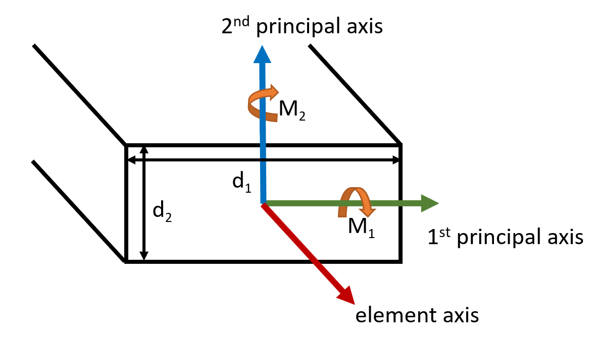
rectangular cross section with pairwise equal thicknesses is calculated as follows:
$$\sigma_b = \frac{d_1}{2I_2}\lvert M_2\lvert + \frac{d_2}{2I_1}\lvert M_1\lvert$$
where
-
$$d_1$$and$$d_2$$are the dimensions of the rectangle along the 1 st and 2 nd principal axes, respecively
-
$$I_1$$and$$I_2$$are the second moments of inertia around the 1 st and 2 nd principal axes, respecively (see Wikipedia)
-
$$M_1$$and$$M_2$$are the bending moments along the 1 st and 2 nd principal axes, respectively.
The picture below illustrates the axes and dimensions of the rectangular cross sections.
Note: to see how the 1
st
and 2
nd
principal axes are defined in Ashes, see
Coordinate systems.
The
Maximum normal stress is defined as the sum of the axial and bending stresses, as
$$\sigma_{norm,max} = \sigma_a + \sigma_b$$
In Ashes, the bending moments are calculated at the two nodes defining an element, which implies that two maximum bending stresses are calculated (one at each node). The maximum of these two is the
Maximum normal stress displayed in the
Beam element sensor.
2 Maximum shear stress
2.1 Shear stress due to shear force
The shear stress due to
shear forces
(as opposed to
torsion) is calculated based on formula 7.3 in
Hibbeler (2013). The maximum shear stress occurs at the neutral axis, and is given by the following formula:
$$\tau_{max,s} = \frac{Vy'A_S'}{Id}$$
where
-
$$V$$is the shear force
-
$$A_S'$$is the structural area above the neutral axis
-
$$y'$$is the distance between the neutral axis and the centroid of$$A_S'$$
-
$$I$$is the second moment of inertia (of the entire cross-sectional area) around the neutral axis
-
$$d$$is the width of the cross section at the neutral axis, perpendicular to the shear force applied. This corresponds to the diameter for a circular cross section (solid or hollow) and to the width or height for a rectangular corss section (depending on the direction of the shear force)
For example, we can calculate the maximum shear stress due to the shear force
$$V$$
on the solid circular cross-section defined in the picture below: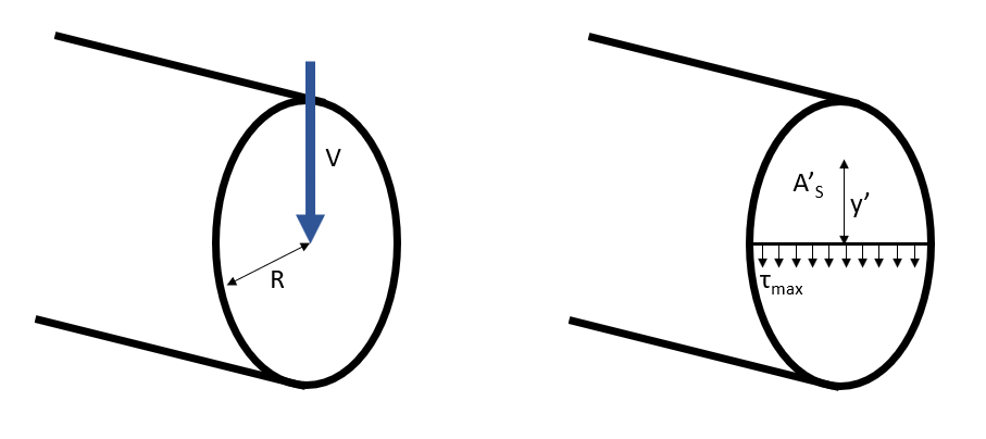
For this case, the second moment of inertia is
$$I = \frac{1}{4}\pi R^2$$
.
The structural area above the neutral axis is
$$A_S ' = \frac{A_S}{2} = \frac{\pi R^2}{2}$$
where
$$A_S$$
is the structural area.
The distance between the neutral axis and the centroid of
$$A_S'$$
is
$$y' = \frac{4R}{3\pi}$$
Then we have
$$\tau_{max,s} = \frac{V\frac{4R}{3\pi}\frac{\pi R^2}{2}}{\frac{1}{4}\pi R^42R}$$
. By rearranging this equation we obtain
$$\tau_{max,s} =\frac{4}{3}\frac{V}{A_S}$$
Similarly, deriving this equation for a
rectangular solid cross section
gives
$$\tau_{max,s} = 1.5\frac{V}{A_S}$$
2.2 Shear stress due to torsion
The maximum shear stress due to torsion in the element is computed with formula 5-6 in
Hibbeler (2013):
$$\tau_{max,t}=\frac{T\cdot R}{J}$$
where
-
$$T$$is the torque applied to the element, i.e. the moment along the axis of the element
-
$$R$$is the radius of the element
-
$$J$$is the polar moment of inertia (see Wikipedia)
The
Maximum shear stress is then calculated as the sum of the maximum stress contributions from the shear force and the torque:
$$\tau_{max} = \tau_{max,s} + \tau_{max,t}$$