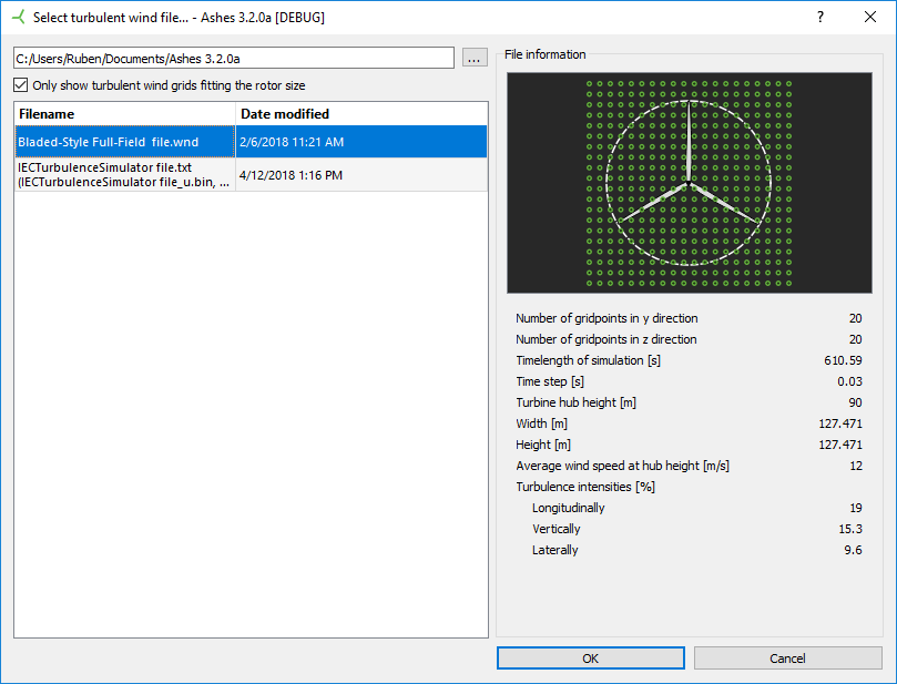
Turbulent wind
- .wnd files generated with TurbSim
- .bin files generated by the Mann turbulence simulator
Source
Source
Select if you want the turbulent wind field to be read from file or generated by Ashes.
Options:
From parameters (default):
The turbulent wind field is generated by Ashes based on the entered parameters.
From file:
The turbulent wind field is read from file.
Turbulent wind file
Choose the file that contains the turbulent wind field. The format must be either
1) TurbSim .wnd, or
2) Mann turbulence generator (also called the IEC Turbulence Simulator) .txt format (which must link to three .bin files).
Turbulent wind fields can be created with the Turbulent wind tool.
If no file is chosen, the wind speed is 0. Clicking this field will open the dialog shown in the picture above.
Note that if you select a turbulent wind field created with TurbSim, the wind speed, wind angle and turbulence intensity is already defined and cannot be changed in the parameter list. These parameters can only be selected for turbulent wind fields created with the Mann turbulence generator.
- Default value:
- Unit: —
Wind general
Average angle
The average angle (direction) of the wind in the horizontal plane relative to North. Clockwise is positive. 0° means that the wind is coming from the North. 90° means that the wind is coming from the East.Note that this is only used for Mann turbulent winds.
- Default value: 0
- Unit: $°$
- Range: -360 — 360
Average wind speed
The average wind speed in the turbulent wind field. Note that this is only used for Mann turbulent winds.
- Default value: 12
- Unit: ${\text{m}} \over {\text{s}}$
- Range: 0 — 1e+08
Shear
Decides if a shear law is applied to the deterministic wind.
- Default value: False
- Unit: —
Power law exponent
The shear is computed using a power law. This is the power law exponent.
To see how the power law is computed, see Wind profile power law
- Default value: 0.2
- Unit: —
- Range: 0 — 100
Grid dimensions
Grid shape
The shape of the turbulent wind grid. Either rectangular or square.
Options:
Square (default):
A square shaped turbulent wind grid.
Rectangular:
A rectangular shaped turbulent wind grid.
Base turbulence grid on model?
Check this parameter to make the turbulent wind grid based on the current model.
- Default value: True
- Unit: —
Reference height scheme
This parameter lets your define whether the point of application of the reference speed (used to compute a vertical wind shear) is input by you or defined as the hub height. This parameter is only relevant if a shear law is applied to the wind.
If Hub height is selected, the reference wind speed for the shear will be applied at hub height. If the turbine has multiple rotors, the reference wind speed will be applied at the average hub height. If there is no rotor, the reference speed is applied at the average height of the nodes at sea level.
Options:
Hub height (default):
The reference height is set to the hub height.
User defined:
The reference height is set explicitly by the user (you).
Reference height
The height above the ground (or above sea level for offshore turbine) where the reference wind speed is applied.
Hub height is often used for the reference height, but in some cases it is convenient to use another height. E.g. if the wind speed is given for a height of 10 m above ground, then this parameter should be set to 10 m. Note: The reference height only has an influence if there is shear (see Wind profile power law)
- Default value: 10
- Unit: $\text{m}$
- Range: 0.01 — 1000
Width of the turbulence grid
The width of the turbulent wind field.
- Default value: 100
- Unit: $\text{m}$
- Range: -1e+07 — 1e+08
Height of the turbulence grid
The height of the turbulent wind grid.
- Default value: 100
- Unit: $\text{m}$
- Range: -1e+07 — 1e+08
Size factor
Determines the size of the turbulence field. For instance, a factor of 2 will generate a field that is twice the width and height of the rotor diameter. The recommended value for onshore turbines is 1.1, while offshore turbines might require larger fields if they are subjected to large displacements and rotations.
- Default value: 1.1
- Unit: —
- Range: 1 — 1000
Horizontal size factor
Determines the size of the turbulence field in horizontal direction. For instance, a factor of 2 will generate a field that is twice the width and height of the rotor diameter. The recommended value for onshore turbines is 1.1, while offshore turbines might require larger fields if they are subjected to large displacements and rotations.
- Default value: 1.1
- Unit: —
- Range: 1 — 1000
Vertical size factor
Determines the size of the turbulence field in vertical direction. For instance, a factor of 2 will generate a field that is twice the width and height of the rotor diameter. The recommended value for onshore turbines is 1.1, while offshore turbines might require larger fields if they are subjected to large displacements and rotations.
- Default value: 1.1
- Unit: —
- Range: 1 — 1000
Grid resolution
The grid resolution type. The turbulent wind grid can either defined by the number of points or by the distances between the points.
Options:
By grid distance:
The number of points is derived by the distance between the points.
By grid points (default):
The distance between the points is defined by the number of points.
Horizontal grid points
The number of grid points of the turbulent wind field in horizontal direction.
- Default value: 32
- Unit: —
- Range: 0 — 64
Vertical grid points
The number of grid points of the turbulent wind field in vertical direction.
- Default value: 32
- Unit: —
- Range: 0 — 64
Horizontal grid distance
The minimum distance between grid points in the turbulence field in horizontal direction. The Turbsim documentation recommends a value equal to the mean chord of the blade. However, the memory requirement of TurbSim scales as the fourth power of the number of grid points, so a very fine-meshed grid for large offshore turbines might not be feasible.
- Default value: 5
- Unit: $\text{m}$
- Range: -1e+30 — 1e+23
Vertical grid distance
The minimum distance between grid points in the turbulence field in vertical direction. The TurbSim documentation recommends a value equal to the mean chord of the blade. However, the memory requirement of TurbSim scales as the fourth power of the number of grid points, so a very fine-meshed grid for large offshore turbines might not be feasible.
- Default value: 5
- Unit: $\text{m}$
- Range: -1e+30 — 1e+23
Turbulence
Turbulence model
Select which turbulence model should be used to generate the turbulent wind field.
Options:
IEC Kaimal model (NTM) (default):
Use the IEC Kaimal model.
IEC Kaimal extreme turbulence (ETM):
Use the IEC Kaimal extreme turbulence (ETM) model.
Von Karman model (IECVKM):
Use the IEC Von Karman model.
Mann turbulence:
Use the Mann turbulence model.
Turbulence intensity category
The turbulence intensity category as defined in IEC 61400-1.
Options:
A (default):
The turbulence intensity Iref is set to 0.16.
B:
The turbulence intensity Iref is set to 0.14.
C:
The turbulence intensity Iref is set to 0.12.
User defined:
The turbulence intensity is defined by you.
Turbulence intensity
The expected value of the turbulence intensity at 15 m/s (in percent), i.e. Iref in IEC 61400-1. A typical interval for turbulence intensity is 10-20%.- Default value: 16
- Unit: $\text{%}$
- Range: 0 — 100
IEC turbine class
The IEC turbine class.
Options:
I (default):
IEC turbine class I
Annual mean wind speed: 10 m/s
50-year extreme wind speed over 10 minutes: 50 m/s
50-year extreme gust over 3 seconds: 70 m/s
II:
IEC turbine class II
Annual mean wind speed: 8.5 m/s
50-year extreme wind speed over 10 minutes: 42.5 m/s
50-year extreme gust over 3 seconds: 59.5 m/s
III:
IEC turbine class III
Annual mean wind speed: 7.5 m/s
50-year extreme wind speed over 10 minutes: 37.5 m/s
50-year extreme gust over 3 seconds: 52.5 m/s
Alfa times epsilon
This parameters scales the intensity of the turbulence. For further explanation the user is refered to the manual of the Mann turbuelnce generator.- Default value: 1
- Unit: —
- Range: 0 — 100
L
The L variable in the Mann turbulence model, corresponding to 0.7-0.8 Λ in IEC61400-1 ed3.
- Default value: 29.4
- Unit: —
- Range: 0 — 100
Gamma
Gamma variable in the Mann turbulence model.
- Default value: 3
- Unit: —
- Range: 0 — 100
Simulation
Seed scheme
Select if you want to enter the seed of the turbulent wind field manually or if it should be randomly generated by Ashes.
Options:
Random (default):
The seed is randomly set based on the current time.
User defined:
You enter the random seed.
Seed
The random seed of the turbulent wind field. Defines the randomness of the internally generated numbers. Using the same random seed twice will give the exactly same turbulent wind field.
- Default value: 1
- Unit: —
- Range: 1 — 1e+08
High frequency compensation
No description yet
- Default value: True
- Unit: —
Time step scheme
Defines if the time step for turbulent wind should be the same as for the FEM analysis or be user defined.
Options:
Use FEM analysis time step (default):
Use same time step as in FEM analysis.User defined:
You define the time step.Turbulence time step
Time step of the turbulent wind field.
- Default value: 0.03
- Unit: $\text{s}$
- Range: 0 — 1e+06
Flow angles
Vertical mean flow angle
The angle of the mean flow in vertical direction.
- Default value: 0
- Unit: $°$
- Range: -90 — 90
Horizontal mean flow angle
Mean flow angle of the turbulent wind field in horizontal direction relative to North.
- Default value: 0
- Unit: $°$
- Range: -360 — 360