- The fields of the Beam element sensor are given in the Element coordinate system (see Coordinate systems)
- The moments along the principal axes are different at the two nodes defining the element. Therefore, two moments, noted i and j, are given for each principal axis
Beam element sensor
The
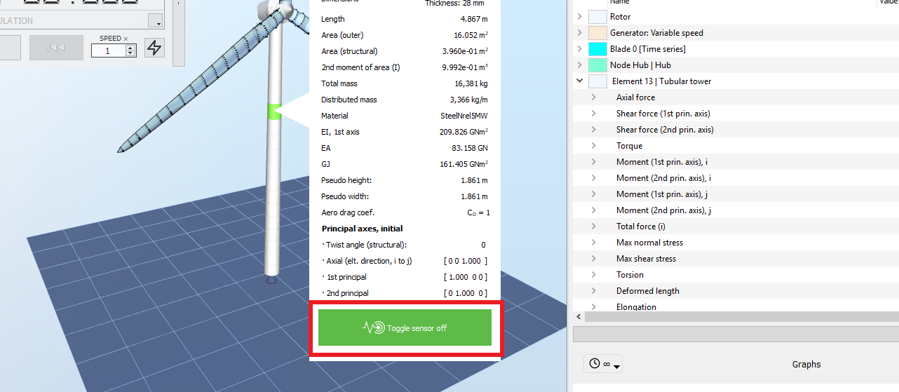
Beam element sensor can be added by right-clicking on the desired element and toggle the sensor on, as shown in the picture below:
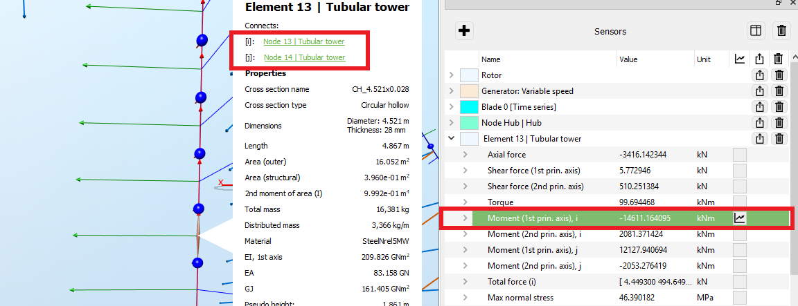
The figure below shows an example of how to interpret the
Moment output around the principal axes and at the different nodes defining the element. In this example, the output analyzed is the
Moment (1st principal axis), i.
-
Right-clicking on the element opens a pop-up window with information about this element. The top of this window shows which nodes are connected to the element and how tey are names. In this example, node
i
of the element corresponds to node
13
of the tubular tower.
- In the Display settings, it is possible to enable the visualization of the Element Coordinate system (see Coordinate systems for more info). The axes defining the element coordinate system are then displayed, with red, green and blue colors corresponding to the axial, the 1 st principal and the 2 nd principal axes respectively. In the present example, the 1 st principal axis is horizontal and perpendicular to the wind (aligned with the global x-axis), as seen in the figure. Note that to facilitate the visualization of the element axes, in this example the wireframe mode has been selected (in the top ribbon of the
The Beam Element sensor provides the following fields. Fields in the
Plastic-hinge diagnostics section are only populated on plastic-hinge beam
elements; on regular elastic beam elements they read zero.
| Field | Unit | Description |
| Axial force | kN | Force along the element axis |
| Shear force (1st prin. axis) | kN | Shear force along the 1st principal axis |
| Shear force (2nd prin. axis) | kN | Shear force along the 2nd principal axis |
| Shear force, mag. | kN | Magnitude of the shear force |
| Torque | kNm | Moment around the axial direction of the element |
| Moment (1st prin. axis), i | kNm | Moment around the 1st principal axis at node i |
| Moment (2nd prin. axis), i | kNm | Moment around the 2nd principal axis at node i |
| Moment, mag., i | kNm | Magnitude of the moment at node i |
| Moment (1st prin. axis), j | kNm | Moment around the 1st principal axis at node j |
| Moment (2nd prin. axis), j | kNm | Moment around the 2nd principal axis at node j |
| Moment, mag., j | kNm | Magnitude of the moment at node j |
| Total force (i) | kN | 3-component vector representing the elastic force at node i |
| Max normal stress mag. | MPa | Maximum stress in the direction parallel to the axis of the element |
| Twist (structural) | deg | The twist of the frame element compared to its initial twist due to rotational deformation (see Frame element twist) |
| Twist (structural) - rad | rad | Same as above, in radians |
| Deformed length | m | Current length of the element, taking account the deformations |
| Elongation | - | Ratio of the deformed length over the initial length |
| Strain energy | J | Elastic strain energy currently stored in the element |
| Kinetic energy | J | Kinetic energy of the element |
| Mechanical energy | J | Sum of the kinetic energy and strain energy of the element |
| Deformational rotation (i) | deg | Magnitude of the rotation of node i relative to the rigid-body rotation of the element (deformation-only component) |
| Deformational rotation (j) | deg | Magnitude of the rotation of node j relative to the rigid-body rotation of the element (deformation-only component) |
| Deformational rotation (axial) | deg | Component of the deformational rotation around the axial direction of the element |
| Deformational rotation (1st prin.) | deg | Component of the deformational rotation around the 1st principal axis |
| Deformational rotation (2nd prin.) | deg | Component of the deformational rotation around the 2nd principal axis |
| Deformational rotation (i) - rad | rad | Same as Deformational rotation (i), in radians |
| Deformational rotation (j) - rad | rad | Same as Deformational rotation (j), in radians |
| Deformational rotation (axial) - rad | rad | Same as Deformational rotation (axial), in radians |
| Deformational rotation (1st prin.) - rad | rad | Same as Deformational rotation (1st prin.), in radians |
| Deformational rotation (2nd prin.) - rad | rad | Same as Deformational rotation (2nd prin.), in radians |
| Damping force, i | kN | Magnitude of the structural damping force at node i |
| Damping moment, i | kNm | Magnitude of the structural damping moment at node i |
| Damping force, sum | kN | Magnitude of the total structural damping force on the element (sum of contributions at nodes i and j) |
| Damping moment, sum | kNm | Magnitude of the total structural damping moment on the element (sum of contributions at nodes i and j) |
| Plastic-hinge diagnostics (populated only on plastic-hinge beam elements; read zero otherwise) | ||
| Plastic rotation (1st prin.), i | rad | Current plastic rotation at the hinge at node i, around the 1st principal axis |
| Plastic rotation (2nd prin.), i | rad | Current plastic rotation at the hinge at node i, around the 2nd principal axis |
| Plastic rotation (1st prin.), j | rad | Current plastic rotation at the hinge at node j, around the 1st principal axis |
| Plastic rotation (2nd prin.), j | rad | Current plastic rotation at the hinge at node j, around the 2nd principal axis |
| Accum. plastic rotation (1st prin.), i | rad | Accumulated absolute plastic rotation (sum of |Δθp|) at the hinge at node i, 1st principal axis |
| Accum. plastic rotation (2nd prin.), i | rad | Accumulated absolute plastic rotation at the hinge at node i, 2nd principal axis |
| Accum. plastic rotation (1st prin.), j | rad | Accumulated absolute plastic rotation at the hinge at node j, 1st principal axis |
| Accum. plastic rotation (2nd prin.), j | rad | Accumulated absolute plastic rotation at the hinge at node j, 2nd principal axis |
| Hinge yielded (1st prin.), i | - | 1 once the hinge at node i (1st principal axis) has yielded (accumulated plastic strain exceeds 1% of the elastic yield strain), 0 otherwise |
| Hinge yielded (2nd prin.), i | - | 1 once the hinge at node i (2nd principal axis) has yielded, 0 otherwise |
| Hinge yielded (1st prin.), j | - | 1 once the hinge at node j (1st principal axis) has yielded, 0 otherwise |
| Hinge yielded (2nd prin.), j | - | 1 once the hinge at node j (2nd principal axis) has yielded, 0 otherwise |
| Effective yield moment (1st prin.), i | kNm | Current yield moment at the hinge at node i (1st principal axis) including isotropic hardening |
| Effective yield moment (2nd prin.), i | kNm | Current yield moment at the hinge at node i (2nd principal axis) including isotropic hardening |
| Effective yield moment (1st prin.), j | kNm | Current yield moment at the hinge at node j (1st principal axis) including isotropic hardening |
| Effective yield moment (2nd prin.), j | kNm | Current yield moment at the hinge at node j (2nd principal axis) including isotropic hardening |
| Moment / yield ratio (1st prin.), i | - | |M| / My,eff at the hinge at node i, 1st principal axis (ratio of current moment magnitude to effective yield moment) |
| Moment / yield ratio (2nd prin.), i | - | |M| / My,eff at the hinge at node i, 2nd principal axis |
| Moment / yield ratio (1st prin.), j | - | |M| / My,eff at the hinge at node j, 1st principal axis |
| Moment / yield ratio (2nd prin.), j | - | |M| / My,eff at the hinge at node j, 2nd principal axis |
| Dissipated energy (sum) | J | Total energy dissipated through plastic deformation, summed over all four hinges of the element |
| Reversal count (1st prin.), i | - | Number of plastic-strain-rate sign reversals observed at the hinge at node i, 1st principal axis |
| Reversal count (2nd prin.), i | - | Number of plastic-strain-rate sign reversals observed at the hinge at node i, 2nd principal axis |
| Reversal count (1st prin.), j | - | Number of plastic-strain-rate sign reversals observed at the hinge at node j, 1st principal axis |
| Reversal count (2nd prin.), j | - | Number of plastic-strain-rate sign reversals observed at the hinge at node j, 2nd principal axis |
Note: the output
Max normal stress and
Max shear stress are only displayed for elements whose cross-section has a known geometry. For the default blades for example, only the outer shape of the blade elements (i.e. the geometry of the airfoils) is known, whereas the internal structure of the blade is now known. Therefore it is not possible to calculate the maximum stresses for blade elements.