Keywords
This section gives a brief explanation of all the keywords used in input files for Ashes. In Ashes, an input file contains several sections defined by a keyword followed by a table with the parameters corresponding to the keyword. In addition, line beginning by the '
#
' sign will not be read by Ashes and can be used to write comment on the file. An example of a section within an input file is given in
Support section files.
Note that in the keyword sections,
- Parameters written in square brackets ( [ ]) are optional
- If optional parameters are left empty, a default value (shown in parenthesis) is applied
- Some keyword sections contain mainy instances of the object created in that section. For example, the Nodes section contains many different nodes, each with its own set of parameters. In that case, each instance starts at a new line.
- Required parameters are the parameters that are necessary to implement an instance within the corresponding keyword section. For example, within the Mooring lines section: if you want your support structure to be connected to mooring lines, you will have to enter a Node name, and an Azimuth angle, as all these two parameters are required. However, you can decide to not have any mooring lines connected to your structure. In that case, the whole Mooring lines section will be left empty.
A list of all the keywords used in the different input files is given here. To see what keywords compose different input file, see the
Support section examples section.
1 Name
The given name appears on the support section that is based on this file.
| Parameter name | Required | Type | Unit | Value if empty | Note |
| Name | yes | String | - | None | - |
If this section is left empty the support section will be named Support section
2 Orientation
A zero rotation will align the axes in the Ashes standard coordinate system; with y
pointing upwind and z pointing up. One method of oriented can be chosen among the following two:
-
Heading: You specify the heading of the y axis (the forward direction) relative to north. A typical case: if you want the structure to have a heading 30 degrees towards the east, enter
Heading 30 -
Angles: You can specify up to three angles, one for rotation about each axis. Each angle represents a right-handed rotation about the axes, in the following order: x (roll), y (pitch), z (yaw). The angles are hence Euler angles. Rotations are intrinsic, which means that successive rotations are performed about the previously rotated axes. To reproduce the previous example where the structure is oriented 30 degrees towards the east, enter
Angles 0 0 30
YesNote that only one type of orientation can be chosen: either
Heading or
Angles.
| Parameter name | Required | Type | Unit | Value if empty | Note |
| Orientation type | Yes | String | - | None |
You can enter 2 options: Heading or Angles
|
| Heading | Yes | Scalar | degrees | None | You can only enter a value for Heading if the Orientation type is set to Heading |
| Roll angle | Yes | Scalar | degrees | None | You can only enter a value for Roll angle if the Orientation type is set to Angles |
| Pitch angle | Yes | Scalar | degrees | None | You can only enter a value for Pitch angle if the Orientation type is set to Angles |
| Yaw angle | Yes | Scalar | degrees | None | You can only enter a value for Yaw angle if the Orientation type is set to Angles |
If this section is left empty, the Heading will be zero. This means that the coordinate system (x, y, z) in which the nodes are defined is the same as the global coordinate system of Ashes, in which the z-axis points upwards and the y-axis points upwind.
3 RNA nodes
RNA is an acronym for Rotor-Nacelle-Assembly. In this section, you can specify which existing nodes (defined in the
Nodes
section) have an RNA. For example, for an RNA connected to the node with the name '10', enter 10 (The node name is alpha-numeric without white space). The normal case is a tubular tower with one RNA on top. To create multi-rotor turbines, you can add new lines, each with the name of a node.
| Parameter name | Required | Type | Unit | Value if empty | Note |
| Node name | Yes | String | - | None | Must be an existing node, defined in the Nodes section |
If this section is left empty, this support structure will have no RNAs. This is generally the case for floaters or other substructures like monopiles, which are connected to a tubular tower but not to an RNA.
4 Tubular tower nodes
A non-tubular tower support section (such as a floater or a monopile) can have one or more tubular towers that are put on top of it.
A support section with one or more tubular towers on top is typically called substructure. In this section, you can s
pecify which nodes have a tubular tower on top.
For example, for an RNA connected to the node with the name '10', enter 10
(the node name is alpha-numeric without white space).
| Parameter name | Required | Type | Unit | Value if empty | Note |
| Node name | Yes | String | - | None | Must be an existing nide, defined in the Nodes section |
If this section is left empty, this support structure will have no tubular tower. Note that a tubular tower cannot have another tubular tower attached to it.
5 Substructure node
A tubular tower on a substructure is connected to the substructure at the Substructure node. This is generally the case for tubular towers connected to monopiles or floaters.
| Parameter name | Required | Type | Unit | Value if empty | Note |
| Node name | Yes | String | - | None |
Must be an existing nide, defined in the
Nodes section
|
6 Mooring lines
A floating wind turbine must have a mooring system consisting of mooring lines.
| Parameter name | Required | Type | Unit | Value if empty | Note |
| Node name | Yes | String | - | None | Must be an existing node, defined in the Nodes section |
| Azimuth angle | Yes | Scalar | Degrees | None | Angle of the line relative to the support section |
If no mooring line is specified, the support section will have no mooring lines. This can be relevant for floaters when the lines are replaced by linear springs, for example.
7 Materials
The elements composing the finite element model defined in the support section file each have material properties. The sets of material properties are called
Materials and are defined in this section.
For each material line, the name, elastic modulus (Young's modulus), Poisson's ratio, and density must be given.
Optionally, the stiffness-proportional damping coefficient (lambda) can be given (if it is not given then there is no material damping).
The name of a material must be unique - and the names are used for the cross sections.
The damping method implemented is the stiffness part of Rayleigh damping (also called proportional damping
).
When a material is defined by the user (you) in the Material tool, the damping ratio (ksi) at a particular frequency are given.
The lambda coefficient is calculated as: lambda = 2*damping ratio/frequency, with frequency as rad/s.
In the Materials tool, however, you can specify the frequency as [Hz].
| Parameter name | Required | Type | Unit | Value if empty | Note |
| Name | Yes | String | - | None |
-
|
| Elastic modulus | Yes | Scalar | Pa | None | Also called Young's modulus. Must be positive. |
| Poisson's ratio | Yes | Scalar | - | None | Must be between 0 and 1 |
| Density | Yes | Scalar | kg.m -3 | None | Must be positive |
| Stiffness proportional damping coefficient (lambda) | No | Scalar | s | 0 | Must be positive |
At least one material per support section must be specified.
8 Cross sections
The cross sections define the properties of the members of the finite element model..
Five kinds of cross sections can be imported/exported, each with their own keyword:
Circular hollow cross sections,
Circular solid cross sections,
Circular shape cross sections,
Rectangular hollow cross sections,
Rectangular shape cross sections and
H cross sections.
The different kinds have some mandatory parameters that are given first in each line.
Additionally, all cross sections have some parameters in common that are all optional and are given after the mandatory parameters.
The following effects can be taken into account with optional parameters:
- Marine growth: to model marine growth, the growth density and its dimater must be defined
- Aerodynamic drag: the aerodynamic drag resulting from the wind and the motion of the structure can be modelled by entering a drag coefficient. A default value of 1 is used in the templates
- Hydrodynamic coefficient: the hydrodynamic inertia and drag forces as calculated from the Morison equation can be modelled by entering the corresponding coefficient.
- Heave plate coefficient: the hydrodynamic inertia and drag forces in the axial direction of the element can be modelled by entering heave plate coefficient.
- Buoyancy tuning: this coefficient multiplies the volume of all members using this cross section. This coefficient is typically used when you are trying to match a given buoyancy with your model and helps accounting for overlapping members, added structures, etc.
At least one cross section must be specified.
8.1 Circular hollow cross section
This is the most widely used type of cross section, especially for tubular towers, monopiles and truss towers. For this type of cross sections, the beam propoerties such as stiffness, moment of inertia or linear mass are calculated depending on the geometric properties and the material.
| Parameter name | Required | Type | Unit | Value if empty | Note |
| Name | Yes | String | - | N/A | - |
| Diameter | Yes | Scalar | m | N/A | Must be positive |
| Thickness | Yes | Scalar | m | N/A | Cannot be more than half the diameter |
| Material | Yes | String | - | N/A | Must correspond to an existing material |
| Growth density | No | Scalar | kg.m -3 | 0 | - |
| Growth thickness | No | Scalar | m | 0 | - |
| Aerodynamic drag coefficient | No | Scalar | - | 0 | - |
| Hydrodynamic drag coefficient | No | Scalar | - | 0 | - |
| Hydrodynamic mass coefficient | No | Scalar | - | 0 | - |
| Heave plate drag coefficient | No | Scalar | - | 0 | - |
| Heave plate mass coefficient | No | Scalar | - | 0 | - |
| Buoyancy tuning factor | No | Scalar | - | 1 | - |
8.2 Circular shape cross section
In this type of cross section, the beam properties such as
stiffness or linear mass are entered by the user. Therefore, knowledge of the geometry of the cross section is not required.
Note that the diameter of the cross section must also be entered. This will be used for visualization and to compute the aerodynamic and hydrodynamic loads, if required. If no aero or hydrodynamic loads need to be included, the corresponding coefficient must be set to 0 and the diameter will have no influence on the simulation results.
| Parameter name | Required | Type | Unit | Value if empty | Note |
| Name | Yes | String | - | N/A | - |
| Diameter | Yes | Scalar | m | N/A | Must be positive. Will be used for visualisation and drag loads (if applicable). |
| Pseudo thickness | Yes | Scalar | m | N/A | Will be used to compute the mass of te filling of the element (if any). The parameter can be ignored by writing 0 or a negative value. |
| Linear mass | Yes | Scalar | kg.m -1 | N/A | Mass per meter of the cross section |
| EI1st | Yes | Scalar | Nm 2 | N/A | Bending stiffness per unit length in the 1st principal direction. Equal to the Young modulus of the material multiplied by the second moment of area. Also called flexural rigidity ( https://en.wikipedia.org/wiki/Flexural_rigidity) |
| EI2nd | Yes | Scalar | Nm 2 | N/A | Idem, second principal direction |
| GJ | Yes | Scalar | Nm 2 | N/A | Torsional stiffness per unit length. Equal to the shear modulus of the material multiplied by the torsional constant. Also called torsional rigidity ( https://en.wikipedia.org/wiki/Stiffness#Relationship_to_elasticity) |
| EA | Yes | Scalar | N | N/A | Axial stiffness per unit length. Equal to the Young modulus multiplied by the area of the cross section ( https://en.wikipedia.org/wiki/Stiffness#Relationship_to_elasticity) |
| GAs,1st | No | Scalar | N | 0 | Shear modulus multiplied by the shear area in the first principal direction. This is relevant when using Timoshenko beam theory (see Euler-Bernoulli and Timoshenko beams) |
| GAs,2nd | No | Scalar | N | 0 | Idem, second principal direction. |
| S_offset, 1st | No | Scalar | m | 0 | Offset of the shear center with respect to the centroid of the cross section in the 1st principal direction |
| S_offset, 2nd | No | Scalar | m | 0 | Idem, 2nd principal direction |
| m_offset, 1st | No | Scalar | m | 0 | Offset of the center of mass with respect to the centroid of the cross section in the 1st principal direction |
| m_offset, 2nd | No | Scalar | m | 0 | Idem, 2nd principal direction |
| Growth density | No | Scalar | kg.m -3 | 0 | - |
| Growth thickness | No | Scalar | m | 0 | - |
| Aerodynamic drag coefficient | No | Scalar | - | 0 | - |
| Hydrodynamic drag coefficient | No | Scalar | - | 0 | - |
| Hydrodynamic mass coefficient | No | Scalar | - | 0 | - |
| Heave plate drag coefficient | No | Scalar | - | 0 | - |
| Heave plate mass coefficient | No | Scalar | - | 0 | - |
| Buoyancy tuning factor | No | Scalar | - | 1 | - |
8.3 Circular solid cross section
This type of cross section is typically used for cables or risers. It is similar to the circular hollow cross section but is solid. Therefore, no thickness is required to define this cross section.
| Parameter name | Required | Type | Unit | Value if empty | Note |
| Name | Yes | String | - | N/A | - |
| Diameter | Yes | Scalar | m | N/A | Must be positive |
| Material | Yes | String | - | N/A | Must correspond to an existing material |
| Growth density | No | Scalar | kg.m -3 | 0 | - |
| Growth thickness | No | Scalar | m | 0 | - |
| Aerodynamic drag coefficient | No | Scalar | - | 0 | - |
| Hydrodynamic drag coefficient | No | Scalar | - | 0 | - |
| Hydrodynamic mass coefficient | No | Scalar | - | 0 | - |
| Heave plate drag coefficient | No | Scalar | - | 0 | - |
| Heave plate mass coefficient | No | Scalar | - | 0 | - |
| Buoyancy tuning factor | No | Scalar | - | 1 | - |
8.4 Rectangular hollow cross section
This type of cross section is similar to the circular hollow cross section but has a rectangular shape. Therefore, many if the parameters must be given in the width and length direction of the cross section. For example, the
Aerodynamic drag coefficient, height specifies the drag coefficient used to compute the drag force for an airflow coming perpendicularly to the
Height
side of the rectangle.
| Parameter name | Required | Type | Unit | Value if empty | Note |
| Name | Yes | String | - | N/A | - |
| Height | Yes | Scalar | m | N/A | Must be positive |
| Width | Yes | Scalar | m | N/A | Must be positive |
| Thickness | Yes | Scalar | m | N/A | Cannot be more than half the diameter |
| Material | Yes | String | - | N/A | Must correspond to an existing material |
| Growth density | No | Scalar | kg.m -3 | 0 | - |
| Growth thickness | No | Scalar | m | 0 | - |
| Aerodynamic drag coefficient, height | No | Scalar | - | 0 | - |
| Aerodynamic drag coefficient, width | No | Scalar | - | 0 | - |
| Hydrodynamic drag coefficient, height | No | Scalar | - | 0 | - |
| Hydrodynamic coefficient, width | No | Scalar | - | 0 | - |
| Hydrodynamic mass coefficient, height | No | Scalar | - | 0 | - |
| Hydrodynamic mass coefficient, width | No | Scalar | - | 0 | - |
| Heave plate drag coefficient | No | Scalar | - | 0 | - |
| Heave plate mass coefficient | No | Scalar | - | 0 | - |
| Buoyancy tuning factor | No | Scalar | - | 1 | - |
8.5 Rectangular solid cross section
This cross section is similar to the rectangular hollow cross section, but no thickness is required.
| Parameter name | Required | Type | Unit | Value if empty | Note |
| Name | Yes | String | - | N/A | - |
| Height | Yes | Scalar | m | N/A | Must be positive |
| Width | Yes | Scalar | m | N/A | Must be positive |
| Material | Yes | String | - | N/A | Must correspond to an existing material |
| Growth density | No | Scalar | kg.m -3 | 0 | - |
| Growth thickness | No | Scalar | m | 0 | - |
| Aerodynamic drag coefficient, height | No | Scalar | - | 0 | - |
| Aerodynamic drag coefficient, width | No | Scalar | - | 0 | - |
| Hydrodynamic drag coefficient, height | No | Scalar | - | 0 | - |
| Hydrodynamic coefficient, width | No | Scalar | - | 0 | - |
| Hydrodynamic mass coefficient, height | No | Scalar | - | 0 | - |
| Hydrodynamic mass coefficient, width | No | Scalar | - | 0 | - |
| Heave plate drag coefficient | No | Scalar | - | 0 | - |
| Heave plate mass coefficient | No | Scalar | - | 0 | - |
| Buoyancy tuning factor | No | Scalar | - | 1 | - |
8.6 Rectangular shape cross section
In this type of cross section, the beam properties such as stiffness or linear mass are entered by the user. Therefore, knowledge of the geometry of the cross section is not required. Rectangular cross sections are used in Ashes to model any cross section that does not have a point symmetry (typically any cross section that is not a circle). In particular, the Rectangular shape cross section is used to model the structural properties of blades (however, the blade structural properties are defined in a Blade structure file).
Note that the height and width of the rectangular cross section must also be entered. This will be used for visualization and to compute the aerodynamic and hydrodynamic loads, if required. If no aerodynamic or hydrodynamic loads need to be included, the corresponding coefficient must be set to 0 and the height and width parameters will have no influence on the simulation results.
| Parameter name | Required | Type | Unit | Value if empty | Note |
| Name | Yes | String | - | N/A | - |
| Height | Yes | Scalar | m | N/A | Must be positive |
| Width | Yes | Scalar | m | N/A | Must be positive |
| Mass | Yes | Scalar | kg.m -1 | N/A | Mass per meter of the cross section |
| EI1st | Yes | Scalar | Nm 2 | N/A | Bending stiffness per unit length in the height direction. Equal to the Young modulus of the material multiplied by the second moment of area in the height direction. Also called flexural rigidity ( https://en.wikipedia.org/wiki/Flexural_rigidity) |
| EI2nd | Yes | Scalar | Nm 2 | N/A | Bending stiffness per unit length in the width direction. Equal to the Young modulus of the material multiplied by the second moment of area in the width direction. Also called flexural rigidity ( https://en.wikipedia.org/wiki/Flexural_rigidity) |
| GJ | Yes | Scalar | Nm 2 | N/A | Torsional stiffness per unit length. Equal to the shear modulus of the material multiplied by the torsional constant. Also called torsional rigidity ( https://en.wikipedia.org/wiki/Stiffness#Relationship_to_elasticity) |
| EA | Yes | Scalar | N | N/A | Axial stiffness per unit length. Equal to the Young modulus of the material multiplied by the area of the cross section ( https://en.wikipedia.org/wiki/Stiffness#Relationship_to_elasticity) |
| GAs, 1st | No | Scalar | N | None | Shear modulus multipled by the shear area in the first principal direction. This is relevant when using Timoshenko beam theory (see the Analysis tab) |
| GAs, 2nd | No | Scalar | N | None | Idem, 2nd principal direction |
| S_offset, 1st | No | Scalar | m | 0 | Offset of the shear center with respect to the centroid of the cross section in the 1st principal direction. |
| S_offset, 2nd | No | Scalar | m | 0 | Offset of the shear center with respect to the centroid of the cross section in the 2nd principal direction |
| m_offset, 1st | No | Scalar | m | 0 | Offset of the center of mass with respect to the centroid of the cross section in the 1st principal direction |
| m_offset, 2nd | No | Scalar | m | 0 | Offset of the center of mass with respect to the centroid of the cross section in the 2nd principal direction |
| Growth density | No | Scalar | kg.m -3 | 0 | - |
| Growth thickness | No | Scalar | m | 0 | - |
| Aerodynamic drag coefficient, height | No | Scalar | - | 0 | - |
| Aerodynamic drag coefficient, width | No | Scalar | - | 0 | - |
| Hydrodynamic drag coefficient, height | No | Scalar | - | 0 | - |
| Hydrodynamic coefficient, width | No | Scalar | - | 0 | - |
| Hydrodynamic mass coefficient, height | No | Scalar | - | 0 | - |
| Hydrodynamic mass coefficient, width | No | Scalar | - | 0 | - |
| Heave plate drag coefficient | No | Scalar | - | 0 | - |
| Heave plate mass coefficient | No | Scalar | - | 0 | - |
| Buoyancy tuning factor | No | Scalar | - | 1 | - |
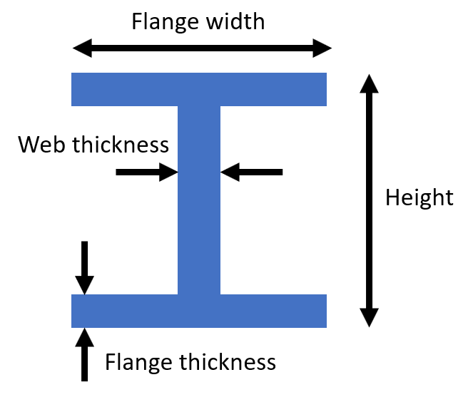
8.7 H cross section
For this cross section, the dimensions as well as the material must be entered. The cross section and its dimensions is illustrated in the figure below:
Optionally,
explicit stiffnesses
can be given (typically found in standard tables), in which case these explicit values are used in the simulations. If they are not given, then the geometry is used to calculate stiffness.
Note: H cross sections cannot be loaded with aero- or hydrodynamical loading
| Parameter name | Required | Type | Unit | Value if empty | Note |
| Name | Yes | String | - | N/A | - |
| Height | Yes | Scalar | m | N/A | Must be positive |
| Flange width | Yes | Scalar | m | N/A | Must be positive |
| Web thickness | Yes | Scalar | m | N/A | Must be less than the Flange width |
| Flange thickness | Yes | Scalar | m | N/A | Must be less than half the Height |
| Material | Yes | String | m | N/A | Must be an existing material |
| Area | No | Scalar | m2 | Calculated | - |
| I1 | No | Scalar | m4 | Calculated | 2nd moment of inertia about the height axis |
| I2 | No | Scalar | m4 | Calculated | 2nd moment of inertia about the width axis |
| Ixy | No | Scalar | m4 |
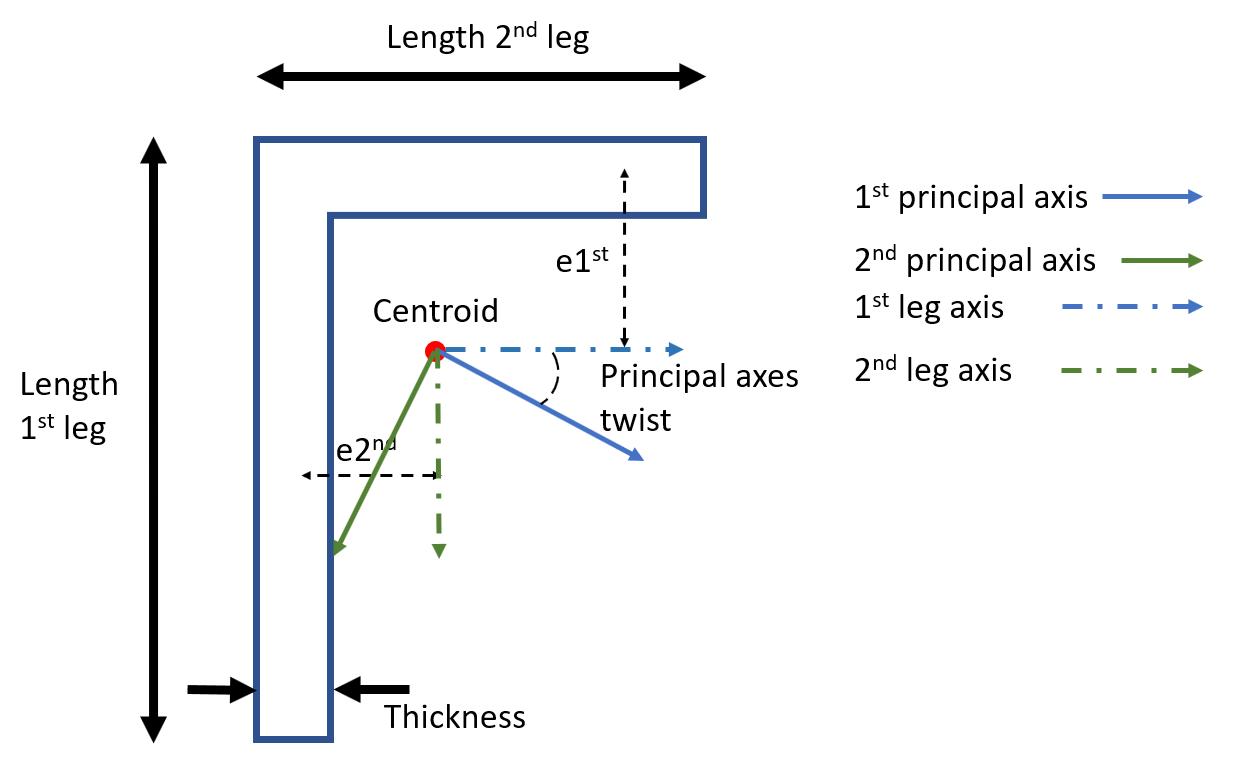
8.8 Angle cross section
For this cross section, the dimensions as well as the material must be entered. The cross section and its dimensions is illustrated in the figure below:
Optionally,
explicit stiffnesses
can be given (typically found in standard tables), in which case these explicit values are used in the simulations. The explicit stiffnesses can either be given for the
geometric axes
or for the
principal axes. The choice is made by the
Axes parameter that can be either 'Geometry' or 'Principal'.
If explicit stiffnesses are not given, then the geometry is used to calculate stiffness (this is the case where no value is given for the parameter
Axes)
Note: angle cross sections cannot be loaded with aero- or hydrodynamical loading
| Parameter name | Required | Type | Unit | Value if empty | Note |
| Name | yes | String | - | N/A | |
| Length 1st leg | yes | Scalar | m | N/A | Must be positive |
| Length 2nd leg | yes | Scalar | m | N/A | Must be positive |
| Thickness | yes | Scalar | m | N/A | |
| Material | yes | String | - | N/A | Must be an existing material |
| Axes | no | String | - | None | Can be either Geometry or Principal |
| e1st | no | Scalar | m | None | Offset of the centroid from the 2nd leg |
| e2nd | no | Scalar | m | None | Offset of the centroid from the 1st leg |
| Area | no | Scalar | m2 | Calculated | |
| I1 | no | Scalar | m4 | Calculated | 2nd moment of inertia about the 1st principal axis (if Principal) or the 1st leg axis (if Geometry) |
| I2 | no | Scalar | m4 | Calculated | 2nd moment of inertia about the 2nd principal axis (if Principal) or the 2nd leg axis (if Geometry) |
| Ixy or alpha | no | Scalar | m4 or degrees | Calculated | Product moment of inertia (if Geometry) or (if Principal) |
9 All sensors
Sensors can be added to nodes, members and supports in the support section text file. The keyword '
All sensors
' offers a shortcut to add sensors to all objects of a particular kind.
The available kinds of object are: elements, nodes, loads, fluid kinematics and supports. If any of these is set to a different value than (the default) 0, then all objects of the kind in question gets a sensor. If instead sensors are wanted for only of a portion of the object in question, the value should be kept at 0 here. The sensors that are wanted are set for the relevant objects at the respective portions of the input file.
| Parameter name | Required | Type | Unit | Value if empty | Note |
| All element sensors | No | String | - | 0 | Any string but 0 means true. |
| All node sensors | No | String | - | 0 | Any string but 0 means true. |
| All node loads sensors | No | String | - | 0 | Any string but 0 means true. |
| All node fluid kinematic sensors | No | String | - | 0 | Any string but 0 means true. |
| All support sensors | No | String | - | 0 | Any string but 0 means true. |
| All linear spring sensors | No | String | - | 0 | Any string but 0 means true. |
| All nonlinear spring sensors | No | String | - | 0 | Any string but 0 means true. |
10 Nodes
This section defines all the nodes that compose the finite element model. Members of the support section can only be defined as going between two nodes.
The node names can be arbitrary alpha-numeric strings without white space.
When exporting a support section, nodes are given increasing integers as names, starting with 1.
The last column [Point mass (kg) = 0] contains point mass for the node in question.
Point mass is optional with a default value of 0. It can be used to define ballast on a floater.
Note:
- Node names must be unique: no two nodes can have the same name
- Node coordinates must be unique: to set up slave nodes, see the Slave nodes section
The coordinates and the rotational point inertias are given in the coordinate system defined in the
Orientation section.
| Parameter name | Required | Type | Unit | Value if empty | Note |
| Node name | Yes | String | - | None | Must be any alpha-numeric string. Whithe spaces are not allowed |
| x | Yes | Scalar | m | None | Coordinate in the x-direction |
| y | Yes | Scalar | m | None | Coordinate in the y-direction |
| z | Yes | Scalar | m | None | Coordinate in the z-direction |
| Point mass | No | Scalar | kg | 0 | Nodes with a point mass will appear grey (and blue if they have no mass) |
| Rotational point inertia, x | No | Scalar | kg.m 2 | 0 | Rotational point inertia around the x-axis |
| Rotational point inertia, y | No | Scalar | kg.m 2 | 0 | Rotational point inertia around the y-axis |
| Rotational point inertia, z | No | Scalar | kg.m 2 | 0 | Rotational point inertia around the z-axis |
| Node sensor | No | String | - | 0 | If set to 1, the node witll have a Node sensor when the file is imported |
| Node load sensor | No | String | - | 0 | If set to 1, the node will have a Loads on node sensor when the file is imported |
| Node fluid kinematic sensor | No | String | - | 0 | If set to 1, the node will have a Fluid kinematics sensor when the file is imported |
At least one node must be defined.
11 Slave nodes
Slave nodes are typically used to create hinges. If a member is connected to a node by a hinge
then the member's start or end node should be a slave node of the (master) node in question.
| Parameter name | Required | Type | Unit | Value if empty | Note |
| Slave node name | Yes | String | - | None | Cannot be the same as the name of another node (master or salve) |
| Master node | Yes | String | - | None | Must be the name of an existing node |
12 Members
The members define the elements of the finite element model. A member is not the same as an element, as a member can be divided into many elements. If a member is divided into elements in the input file, Ashes will automatically create the necessary nodes when importing the file. If the support section is then exported from Ashes, all the newly created nodes and members will appear in the exported text file.
It can be necessary to rotate members along their axis for rectangular elements or to adjust the element sensor to a given requirement.
When checking an
Beam element sensor
, the results are given within the element coordinate system defined by the axial direction (red vector), first principal direction (green vector) and the second principal direction (blue vector. To visualize the element coordinate system check the
Display settings
). The member and its coordinate system can be rotated around the axial direction by changing the value of the
Initial direction
optional parameter. By default, the initial position is such that
-
the axial direction is from the first node defining the member to the second node
-
the second principal axis is horizontal
-
the first principal axis forms a right-handed coordinate system. Therefore, the first principal axis has the maximum gradient upwards or downwards, depending on the axial direction..
If the axis of the element is vertical, the first principal axis point in the x-direction as defined in the
Orientation section of the input file. See
Coordinate systems for more information.
Filling of a member (parameters
Filling density
and
Filling portion) is specified per member (see table below) as opposed to (external) growth that is specified for the cross section.
| Parameter name | Required | Type | Unit | Value if empty | Note |
| Member name | Yes | String | - | None | Must be an alphanumeric string. White spaces are not allowed |
| Start node | Yes | String | - | None | - |
| End node | Yes | String | - | None | - |
| Cross section | Yes | String | - | None | Must be an existing cross section, defined in the input file |
| Number of elements | No | Integer | - | 1 | The member will be divided into this number of elements in Ashes |
| Initial rotation | No | Scalar | Degrees | 0 | - |
| Filling density | No | Scalar | kg.m -3 | 0 | For hollow elements, the hollow part can be filled with a material which density is given here. Typically, this is used for waterfilling in offshore structures. |
| Filling portion | No | Scalar | - | 1 |
The portion of the hollow part that is filled. 1.0 means that it is completely filled (100%), 0.0 means that it is completely empty.
|
| Beam Sensor | No | String | - | 0 | If set to 1, the corresponding member will have a sensor when the file is imported. |
| Fatigue sensor | No | String | - | 0 | The string will define where on the member the stresses will be computed. See note below for an explanation of the format |
Note: the format of the string defining the fatigue sensor is
node_name&position1@position2@position3@...
- the node name will be either i, j or ij (corresponding to the nodes composing the element, which can be seen by right-clicking the element)
- the position corresponds to the angular position in degrees where the stress will be computed. The angle is given from the 1st principal axis of the element and with a positive angle being towards the 2nd principal axis (see section 3. Element coordinate system of the Coordinate systems document)
A fatigue sensor string can therefore look like
ij&0@180, or like
i&10@20@30@40
If no members are defined, the model will only be composed of nodes and no elements.
13 Supports
Supports enable you to define how the support section is attached to the non-moving reference frame. A support is defined by constraining some of the degrees of freedom of a node chosen by the user. Two type of supports can be defined:
- Fixed: the translations and rotations of the node are constrained
- Pinned: the translation of the node are constrained, the rotations are free.
| Parameter name | Required | Type | Unit | Value if empty | Note |
| Name | Yes | String | - | None | Must be an alphanumeric string. White spaces are not allowed |
| Type | Yes | String | - | None | Must be either Pinned or Fixed |
| Node name | Yes | String | - | None | Must be an existing node name |
| Sensor | No | String | - | 0 | If set to 1, the corresponding support will have a sensor when the file is imported |
If no support is defined, none of the nodes of the support section will have its degrees of freedom constrained. However, it is still possible to define an interaction between the support section and the non-moving referenece frame by using
Mooring lines or
Springs.
14 Springs
The support section can be attached to the non-moving reference frame by adding linear springs to given nodes. This springs can be of two types:
- Springs: linear translational spring
- RotationalSpring: linear rotational spring
Note: the stiffnesses and rotational stiffnesses are given in the global coordinate system
| Parameter name | Required | Type | Unit | Value if empty | Note |
| Name | Yes | String | - | None | Must be an alphanumeric string. White spaces are not allowed |
| Type | Yes | String | - | None | Must be either Spring or RotationalSpring |
| Node name | Yes | String | - | None | Must be an existing node name |
| Stiffness x-direction | Yes | Scalar | N.m -1 or Nm.rad -1 | None | Stiffness along the x-direction for a translational spring, around the x-direction for a rotational spring |
| Stiffness y-direction | Yes | Scalar | N.m -1 or Nm.rad -1 | None | Stiffness along the y-direction for a translational spring, around the y-direction for a rotational spring |
| Stiffness z-direction | Yes | Scalar | N.m -1 or Nm.rad -1 | None | Stiffness along the z-direction for a translational spring, around the z-direction for a rotational spring |
| IsPy? | No | Boolean | - | 0 | Tags a spring as Py if set to 1. This does not influence the simulation but is used to track which loads come from P-y curves in the Total loads sensor |
| Sensor | No | String | - | 0 | If set to 1, the corresponding support will have a sensor when the file is imported |
15 Nonlinear springs
It is possible to implement non-linear springs as p-y curves. In order to do that, a new section named
Table must be created for each p-y curve. This section will contain the different tables that define the non-linear stiffness curves. Then, the section
Nonlinear springs will link each node where a p-y curve must be applied to those tables.
The code snippet below shows an example of how p-y curves can be defined (such an example can be found by clicking
Help-> Open Examples Folder)
1
2
3
4
5
6
7
8
9
10
11
12
13
14
15
16
17
18
19
20
21
22
23
24
25
26
27
28
29
30
31
32
33
34
35
36
37
38
39
40
41
42
43
# About Nonlinear springs
# Nonlinear translational springs with the given direction in global coordinates and where the stiffness relation is given in
#  a table in a Table section.

Nonlinear springs
# Name    Type 	Node name	x-direction (m) 	y-direction (m). 	z-direction (m)	Stiffness table name 	[IsPy ? = 0 (-)]
Nonlin1x   Spring	M1	1	0	0	PyCurve1	1
Nonlin1y   Spring	M1	0	1	0	PyCurve2	1

# About tables
# A table can contain various data that can be used in multiple contexts.
#
# A table entry should specify the header in the following layout:
#
# Table
# <UniqueName>
# <Key label>	<Value1 label>	<Value2 label>	...
# <[Key dimensions]>	<[Unit1 dimensions]>	<[Unit2 dimension]>	...
# <Key1>	<Value1_1>	<Value1_2>	...
# <Key2>	<Value2_1>	<Value2_2>	...
# ...	...	...	...
#
# Refer to the documentation for help with specifying units. Optionally, insert a "[]" string
# for each column to define the values as unitless. Note: The unit does not matter for a nonlinear
# spring stiffness table.
# The table data should follow after the header as a table of values with the same
# number of columns as specified in the header.

# First table
Table
PyCurve1
Displacement	SpringLoad
0	0
0.5	10000
1.0	500000

# Second table
Table
PyCurve2
Displacement	SpringLoad
0	0
0.5	20000
1.0	100000
Note: a linear interpolation is performed to obtain the force at a given displacement. This is equivalent to taking a linear spring with an effective stiffness between two points defined in the table. In the example in the picture above, if the displacement of node 'M1' in the y-direction is between 0 and 0.5 m, the table PyCurve2 shows that the effective stiffness will be (20 000 - 0)/(0.5 - 0) = 40 000N.m
-1.
The directions in which the p-y curves are applied to the different nodes are given in the global coordinates system.
| Parameter name | Required | Type | Unit | Value if empty | Note |
| Name | Yes | String | - | None | Must be an alphanumeric string. White spaces are not allowed |
| Type | Yes | String | - | None | Must be either Spring or RotationalSpring |
| Node name | Yes | String | - | None | Must be an existing node name |
| x-direction | Yes | Scalar | m | None | x-coordinate for the non-linear spring |
| y-direction | Yes | Scalar | m | None | y-coordinate for the non-linear spring |
| z-direction | Yes | Scalar | -m | None | z-coordinate for the non-linear spring |
| Stiffness table name | Yes | String | - | None | Refers to a table defined in the Table section |
| IsPy? | No | Boolean | - | 0 | Tags a spring as p-y if set to 1. This does not influence the simulation but is used to track which loads come from P-y curves in the Total loads sensor |
| Sensor | No | Boolean | - | 0 | If set to 1, the corresponding spring will have a sensor when imported |
For a nonlinear translational spring, the units of the table are
meters and
Newtons.
For a nonlinear rotational spring, the units of the table are
radians and
Newton-meters.
16 Damping loads
Damping can be implemented as (nonlinear) loads.
The damping factor is multiplied with the velocity of the node in question to give a damping load
in the opposite direction.
| Parameter name | Required | Type | Unit | Value if empty | Note |
| Node name | Yes | String | - | None | Must be an existing node name |
| Damping factor | Yes | Scalar | Ns.m -1 | None | - |
17 Transforms
The support section structure can be scaled, translated or rotated by defining one or more transformations.
Valid transforms are scale, translate and rotate. The transformations will be applied in the order specified.
Note that if this structure is imported onto another structure, translations will be ignored,
since the structure will be connected to the existing one.
Examples
-
To translate the structure 20 meters in the x-direction and 10 meters in the y-direction, type
12Transforms Translate 20 10 0 -
To rotate the structure 90 degrees around the x-axis, type
12Transforms Rotate 90 0 0 -
To scale the structure to 50% while keeping the node 12 fixed, type
12Transforms Scale 0.5 Node 12
18 Line sections
This section is only used for
mooring lines
input files.
Each text line defines the position (in meters) for nodes along the mooring line, starting from the anchor node
to the fairlead node connected to the floating platform. As a minimum, one station for the 0 position
and one for the end position (with position equal to the line length) should be specified.
Note: Only the x value (the position along the line) is used in this section, y and z is ignored. Ashes will lay out the line structure in a catenary shape when imported.
It is recommended to check the final length on the information pane on the generated line to see if it is sufficiently close to the length you have specified. If it's not, try to increase the number of stations
| Parameter name | Required | Type | Unit | Value if empty | Note |
| Line position | Yes | Scalar | m | None | Position along the line |
| Cross section | Yes | String | - | None | Must be an existing cross section defined in the Cross sections section |
| Point mass | Yes | Scalar | kg | None | Nodes with a point mass will appear grey in Ashes (and blue otherwise) |