Blade shear center offsets
1 Test description
This test uses a simple blade composed of one airfoil to verify the influence of the elastic, shear and mass offsets. These offsets are defined in the
Blade structure file. For the test we take the characteristics of the half-blade section of the
DTU 10-MW. This corresponds to an
FFA-W3-241
airfoil. The blades do not rotate. The gravitational acceleration is
$$g = 9.80665\text{ m}\cdot{s}^{-2}$$
.
The blade has a projected length of 10 meters (see
Blade length) and is divided into 4 elements.
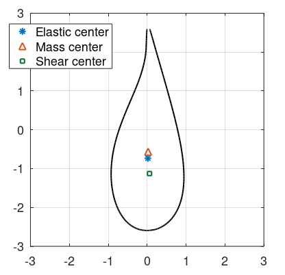
The offsets are defined as follows:
|
ElasticCenterOffsetX
$$e_x$$
|
ElasticCenterOffsetY
$$e_y$$
|
MassCenterOffsetX
$$m_x$$
|
MassCenterOffsetY
$$m_y$$
|
ShearCenterOffsetX
$$s_x$$
|
ShearCenterOffsetY
$$s_y$$
|
| 0.7349 m | 0.0189 m | 0.5665 m | 0.025 m | 1.1275 m | 0.0611m |
The offsets are given from the
chordline mid-point, and are positive towards the leading edge and towards the suction side. The airfoil is shown in the figure below:
To assess wether the offsets are applied correctly, we apply different loads and analyse the value of the
Root torque of the blade, from the
Blade [Time] sensor.
The blade has no
In-plane or
Out-of-plane pre-bend, therefore the pitch axis goes through the chordline mid-point (see
Blade structure file). This implies that the bending moment at the root of the blade (i.e te
Root torque)
will be produced by the offsets between the point of application of the aerodynamic loads and the chordline mid-point.
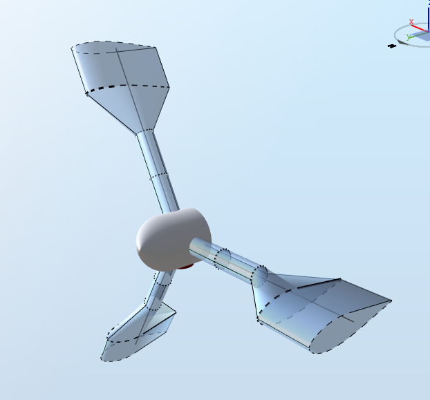
The first node (at the blade root) cannot have structural offsets in Ashes. In order to simplify the test, we only generate aerodynamic loads towards the tip of the blade. This is done by having a circular cylinder with drag and lift coefficients equal to 0 towards the root. This produces the following, somewhat exotic, blade:
No hub or tip loss is applied. The blades are pitched so that the chordline is aligned with the wind. The chord length of the blade stations with a non-circular airfoil is
$$c=5.190\text{ m}$$
. The air density is
$$\rho = 1.225\text{ kg}\cdot\text{ m}^{-3}$$
2 Analytical results
The blade are not rotating, so the angle of attack is
$$\alpha = 0$$
. For the FFA-W3-241 airfoil, this produces a lift and a drag coefficient of
$$C_L = 0.339$$
and
$$C_D=0.0092$$
, respectively.
For a wind speed
$$V = 10\text{ m}\cdot\text{s}^{-1}$$
, this produces a linear lift and drag force of
$$dF_L = \frac{1}{2}\rho cC_LV^2=107.8\text{ N}\cdot\text{m}^{-1}$$
and
$$dF_D = \frac{1}{2}\rho cC_LV^2=2.925\text{ N}\cdot\text{m}^{-1}$$
The two outer Blade aerodynamical stations combine for an
Influence length
$$L_I = 3.75\text{ m}$$
. Therefore, the lift and drag forces on the blade will be
$$F_L=dF_L\cdot L_I=404.1\text{ N}$$
and
$$F_D = dF_D\cdot L_I = 10.97\text{ N}$$
This gives a Root force magnitude of
$$F_R=\sqrt{F_L^2+F_D^2}=404.2\text{ N}$$
Since the rotor is not rotating, the thrust force is going to be equal to the sum of the drag forces on the three blades:
$$F_T=3\cdot F_D=32.90\text{ N}$$
.2.1 Forces applied to the aerodynamical reference point
The image below illustrates the situation where the aerodynamic forces are applied onto the
Aerodynamical reference point.
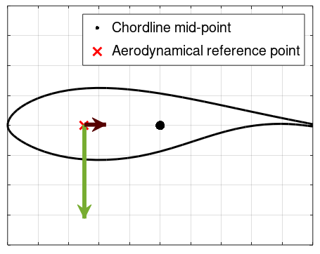
The lift force is drawn in green and the drag force in brown (not to scale)
The offset between the aerodynamical reference point and the chordline mid-point for this airfoil is
$$a_x = 0.25c$$
. Note that there is only an offset along the chordline (i.e. parallel to the drag force) and not perpendicular to it, which means that only the lift force will contribute to creating a pitching moment (or torque) on the blade. The torque at the root of the blade will thus be equal to
$$a_x\cdot F_L$$
. The positive torque direction is from the root to the tip of the blade, and the
Root torque field of the
Blade [Time] sensor corresponds to the
response torque. Therefore, we expect a negative root torque equal to
$$T_R = -a_x\cdot F_L=-524.3\text{ Nm}$$
2.2 Forces applied to the elastic center
The image below illustrated the situation where the aerodynamic forces are aplied onto the
Elastic center.
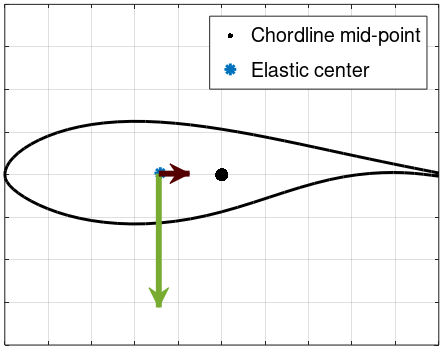
The elastic center is offset from the chordline mid-point both in the directions of the lift and the drag force, The root torque is now expected to be
$$T_R = -F_L\cdot e_x+F_D\cdot e_y=-296.8\text{ Nm}$$
(Note that the lift and the drag contribute to the root torque in opposite directions)
2.3 Shear center applied
In this situation, the aerodynamical forces are again applied at the Aerodynamical reference point, but the shear center is taken into account. This is illustrated in the figure below.
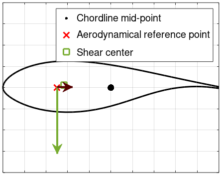
Because the shear center is offset from the point of application of the forces, an additional torque will appear, equal to
$$T_S = -F_L\cdot(a_x-s_x)-F_D\cdot(s_y)=-69.27\text{ Nm}$$
This will be in addition to the torque obtained in the case where we don't consider the shear center. The total root torque will therefore be
$$T_R = -524.3-69.27=-593.6\text{ Nm}$$