Aerodynamical reference point eccentricity
1 Test description
The aim of this model is to check whether the influence of the
Aerodynamical reference point is correctly captured at the blade root.
The following load cases are tested:
- No eccentricity
- Aerodynamical reference point
- Moment coefficient
- Aerodynamical reference point and moment coefficient
2 Model
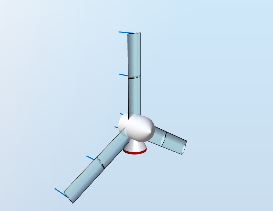
This test uses a blade with a constant airfoil. The rotor does not rotate and has no tilt or cone. Gravity loads are disabled and a constant uniform wind is applied. The model is shown in the figure below:
The airfoil used for the blades is the
NACA64-618 airfoil used for the NREL-5 MW reference blade. This airfoil has the Aerodynamical reference point located 0.25 chord lengths away from the leading edge, as indicated by the red X in the figure below:
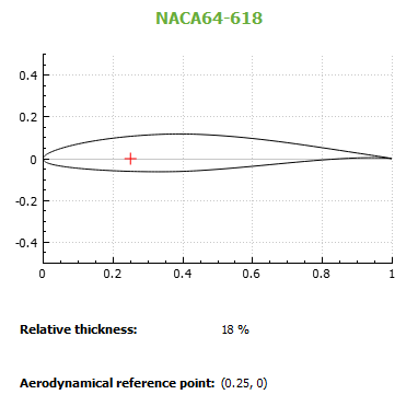
Note that the aerodynamical reference point is on the chord line, i.e. there is no offset in te direction perpendicular to the chord line.
The chord length is constant across the blade span and equal to
$$c = 1\text{ m}$$
. The hub has a radius
$$r_H = 0.5\text{ m}$$
.
The blade has a length
$$L = 5\text{ m}$$
and is composed of 2 elements. This implies that there are three
Blade aerodynamical station:
Blade station1
at the root,
Blade station 2
located 2.5 meters away from the root (at half-span) and
Blade station 3
at the tip. The root and tip blade aerodynamical stations have an
Influence length
$$L_{I1}=L_{I2}=1.25\text{ m}$$
, the one at half-span as an influence length
$$L_{I3}=2.5\text{ m}$$
. The table below gives a summary of the relevant blade characteristics:
| Blade aerodynamical station | Distance to root | Influence length |
| 1 |
$$r_1=0$$
|
$$L_{I1}=1.25\text{ m}$$
|
| 2 |
$$r_2 = 2.5\text{ m}$$
|
$$L_{I2}=2.5\text{ m}$$
|
| 3 |
$$r_3 = 1.25\text{ m}$$
|
$$L_{I3} = 1.25\text{ m}$$
|
Since the rotor is not rotating, the angle of attack at each blade station will be constant and equal to 90 degrees. The aerodynamic coefficients will therefore also be constant and, for 90 degrees, are
$$C_L = 0.053$$
,
$$C_D = 1.4565$$
and
$$C_M = -0.3858$$
.
The air density is
$$\rho = 1.225\text{ kg}\cdot{m}^{-3}$$
and the wind speed is constant at
$$V = 10\text{ m}\cdot{s}^{-1}$$
3 Analytical solution
For all the load cases, the Blade stations will experience linear lift and drag forces equal to
$$dF_L = \frac{1}{2}\rho\cdot c\cdot C_L\cdot V^2$$
$$dF_D = \frac{1}{2}\rho\cdot c\cdot C_D\cdot V^2$$
$$F = \Sigma_{i=1}^3\sqrt{(dF_L\cdot L_{Ii})^2+(dF_D\cdot L_{Ii})^2} = 446.3\text{ N}$$
The blade is not rotating, which implies that the lift and the drag forces are in the in-plane and out-of-plane directions, respectively. The in-plane bending moment at the root of the blade can therefore be calculated as
$$M_{IP}=\Sigma_{i=1}^3F_L\cdot L_{Ii} \cdot r_i=40.57\text{ Nm}$$
The out-of-plane bending moment at the root of the blade will be
$$M_{OOP}=\Sigma_{i=1}^3F_D\cdot L_{Ii} \cdot r_i=1115\text{ Nm}$$
And the magnitude of the root moment will be
$$|M|=\sqrt{M_{IP}^2+M_{OOP}^2}=1116\text{ Nm}$$
These results can be obtained with the
Blade [Time] sensor.
We can also derive results at rotor level. The total aerodynamic thrust will result from the drag on all three blades and therefore be equal to
$$F_{T} = 3\cdot\Sigma_{i=1}^3F_D\cdot L_{Ii} = 1338\text{ N}$$
The total aerodynamic torque will result from the lift on all three blades.
$$T = 3\cdot\Sigma_{i=1}^3F_L\cdot L_{Ii}\cdot (r_i+r_H) = 146\text{ Nm}$$
These results can be obtained with the
Rotor sensor.
3.1 No eccentricity
In this test, the aerodynamic loads are applied on the
elastic center, by selecting the corresponding option for the
Force center parameter in the
Blade modeling section of the
Aerodynamics tab. In addition, the effect of the moment coefficient of the airfoil is disabled.
Because the blade has no structural offsets or prebend, the elastic center is on the pitch axis. Therefore, the aerodynamic loads on each Blade aerodynamical station will not produce any moment along the pitch axis of the blade.
Because the blade has no structural offsets or prebend, the elastic center is on the pitch axis. Therefore, the aerodynamic loads on each Blade aerodynamical station will not produce any moment along the pitch axis of the blade.
It is thus expected that the
Root torque output of the
Blade [Time] sensor will be zero.
3.2 Aerodynamical reference point
In this test, the aerodynamic loads are applied on the
Aerodynamical reference point. Since there is no prebend, and as explained in the
Blade structure file document, the pitch axis goes through the
chord line midpoint of the airfoil. The point of application of the aerodynamic loads is therefore
$$0.25\cdot c = 0.25\text{ m}$$
away from the pitch axis towards the leading edge. Since this point of application is on the chordline, only the drag force will produce a moment. The drag force, illustrated by the blue vector in the figure below, will produce a moment around the pitch axis positive in the vertical direction.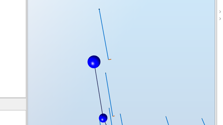
The
Root torque from the
Blade [Time] sensor, which corresponds to the reaction torque at the root around the pitch axis, will therefore be
negative and equal to
$$T_R = -0.25\cdot\Sigma_{i=1}^3F_D\cdot L_i = -111.5\text{ Nm}$$
More details about the sign of the r
oot torque can be found in the
Blade [Time] sensor document.
Note that the magnitude of the root moment now includes the root torque and will thus be equal to
$$|M| = \sqrt{M_{IP}^2+M_{OOP}^2+T_R^2}=1121\text{ Nm}$$
3.3 Moment coefficient
In this test, the
moment coefficient is applied, but the offset of the aerodynamical reference point is disabled. Similarly to the lift and drag forces, the linear aerodynamic moment will be
$$dM = \frac{1}{2}\rho\cdot c\cdot C_M\cdot V^2$$
This will be producing a moment equal to
$$dM\cdot(L_{I1}+L_{I2}+L_{I3})=-118.2\text{ Nm}$$
.
As explained in the previous test, the
Root torque output of the
Blade [Time] sensor corresponds to the reaction torque at the root, and will therefore have the opposite sign. It will thus be equal to
$$T_R = 118.2\text{ Nm}$$
and the magnitude of the root moment will be
$$|M| = \sqrt{M_{IP}^2+M_{OOP}^2+T_R^2}=1122\text{ Nm}$$
3.4 Aerodynamical reference point and moment coefficient
In this test, the influence of both the
moment coefficient and the
aerodynamical reference point are considered. The
root torque will therefore be
$$T_R = 188.2-111.5 = 6.638\text{ Nm}$$
and the magnitude of the root moment will be
$$|M|=1115\text{ Nm}$$
4 Results
In addition to the model described here, we run this test as a
static simulation and with a blade that has 10 structural nodes instead of 2.
For each test, a simulation of five seconds is run. The test is considered passed if the last 20% of the times series from Ashes lie within 0.05% of the analytical solution.
The reports for each test can be found on the following links: