Xfoil
Xfoil is a program for the design and analysis of airfoils, that can be downloaded from the following link:
https://web.mit.edu/drela/Public/web/xfoil/. Xfoil can be used in two contexts in Ashes:
1 Investigate airfoil
The
Investigate airfoil dialog can be accessed from the
Airfoil database. This enables you to study how the pressure is distributed along the airfoil for different values of the Reynolds number, Mach number, Ncrit and angle of attack. These four parameters are set by you.
All other parameters are equal to the default values in Xfoil.
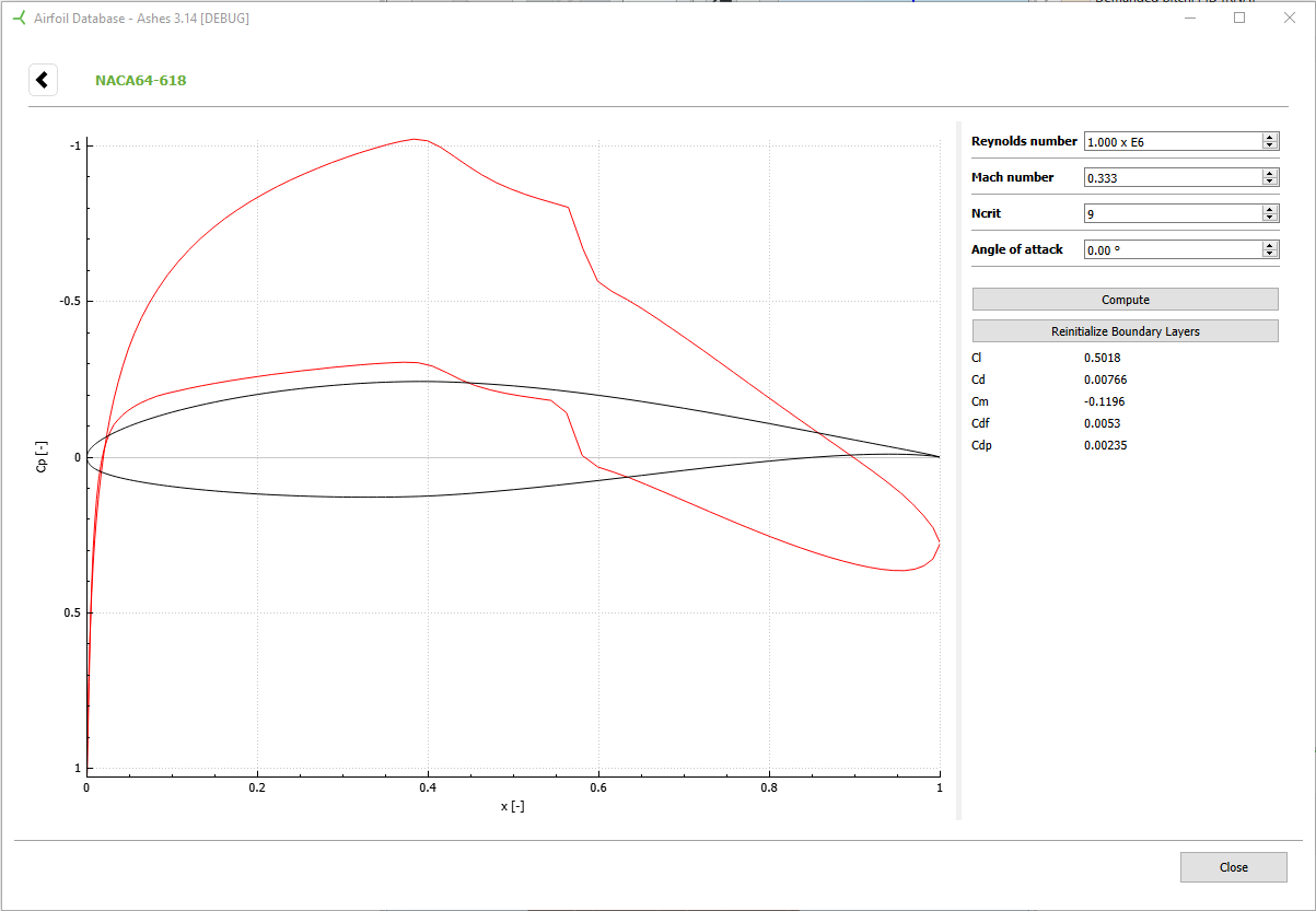
The figure below shows an example of the
Investigate airfoil for the NACA64-618:
In order to reproduce these results with Xfoil, you would need to go through the following steps:
- Open Xfoil
- Load the corresponding airfoil (note that the Xfoil format is slightly different than the Ashes format)
- type oper to go to the operating points menu
- type visc to toggle the Viscous mode
- you will be asked for a Reynolds number. Type in 1000000
- The Reynolds number is now set. To modify the Mach number, type M 0.333
- type vpar to change the boundary layer parameters menu
- type N 9 to change Ncrit to 9
- press enter to go back to the oper menu
- type alfa 0 to run the computation
Note: if the computation does not converge, you can keep iterating by retyping
alfa 0. This will rerun the computation, using the latest iteration as the initial condition for the next computation. You can do the same thing in Ashes by pressing
Compute again. You can also reinitialize the boundary layers by typing
init. In Ashes you can click on the button
Reinitialize Boundary Layers.
2 Generate polar
Ashes also provides the possibility to generate polars. In that case, the process of runing the commands described in the section above is automated for the parameters specified. Some additional commands are or can be perfomed, listed below:
2.1 Smoothening airfoil
This process is always performed when generating polars. It is equivalent to running the following steps.
- from the main Xfoil menu, go to the mdes menu
- run the filt command to apply Hanning filter (see http://web.mit.edu/drela/Public/web/Xfoil/xfoil_doc.txt for more info)
- run the exec command to execute the calculation. This will slighty modify the surface speed distribution around the airfoil. This modification is applied to a buffer aitfoil, i.e. a copy of the current airfoil.
- go back to the main menu by pressing enter
- run the pane command to aply the modifications to the current airfoil
2.2 Forcing transition
It is possible to force the boundary layer to transition from laminar to turbulent flow by ticking the
Leading edge roughness box as shown in the figure below.
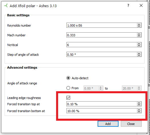
Selecting
Leading edge roughness and setting the values to 0.1% and 10% is equivalent to running the following steps:
- from the main Xfoil menu, run oper to go to the operating points menu
- run vpar to go to the boundary layer parameters menu
- run xtr 0.001 0.1 to change the transition points
2.3 Auto-detection of angle of attack range
If the
Angle of attack range is set to
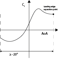
Auto-detect, the algorithm first tries to find the smallest negative angle of attack that the Xfoil computations converge for. However, this minimum angle cannot deceed
-20 degrees. This angle of attack is then used as a starting point for the polar. The upper limit of the range is the
leading-edge separation angle, i.e. the angle where the lift curve reaches its local minimum just after maximum C
l. This angle is suggested as the point from which on the Viterna extrapolation method can be applied according to
Tangler et al. (2004a) (see
Figure 1).
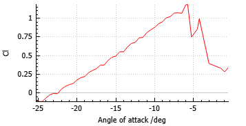
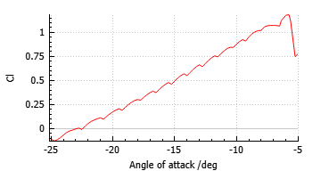
The lift curve is smoothened by applying a movering average over the last, the current and the next angle of attack. Hence, if a too great step of angle of attack is chosen, the algorithm might not work as expected and miss the leading-edge separation point (see
Figure 2). In this case it is recommended to set the step smaller (see
Figure 3).
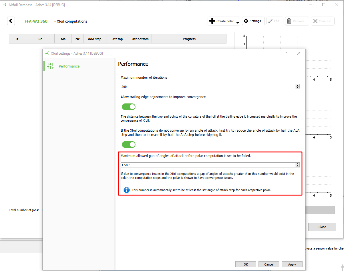
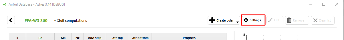
2.4 Performance settings
You can change some settings that have an impact on how Xfoil is performing, i.e. if computations of polars do converge or not. In order to open the respective dialog, click on the
Settings button.
2.4.1 Change maximum number of iterations
The maximum number of iterations before a computation is considered not having converged can be set.
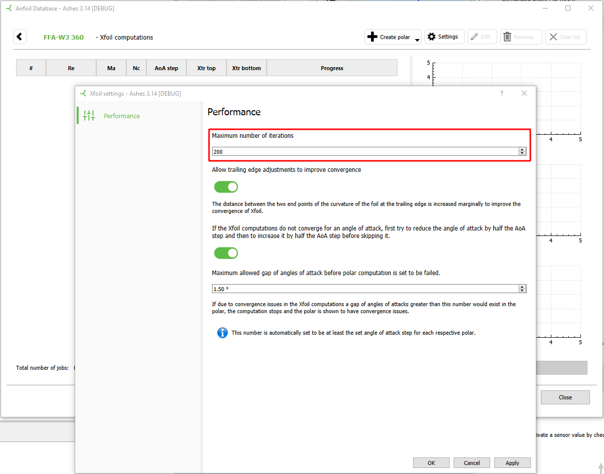
This is equivalent to the following steps in Xfoil:
- from the Xfoil menu, run oper to go to the operating points menu
- run iter n, where n is the maximum number of iterations
2.4.2 Allow trailing edge adjustments
If the Xfoil computations don't converge, it is possible to slightly modify the geometry of the airfoil at the trailing edge to improve convergence. This can be done by toggling on
Trailing edge adjustments in the settings, as shown in the figure below:
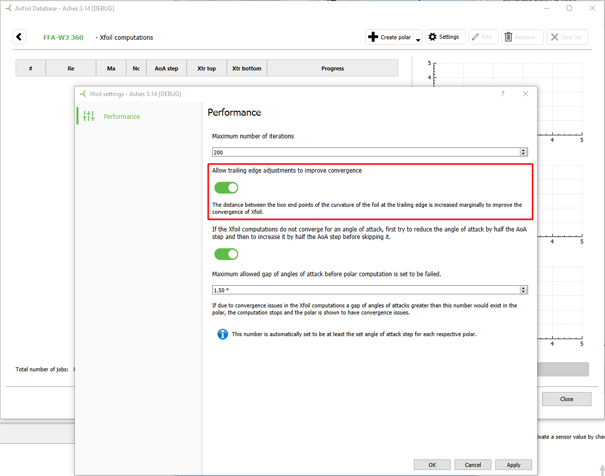
Toggling this option on will modify the geometry of the airfoil only when convergence for a given angle of attack is not reached. In that case, the following steps are taken:
- from the main Xfoil menu, run gdes to open the geometry design routine menu
- run tgap x 1 to modify the gap at the trailing edge of the airfoil.
The value x in the
tgap command is varied from 0 to 0.0006 in steps of 0.0001 to improve convergence. If convergence is still not achieved, Ashes returns a
Non-converged error message.
2.4.3 Increase and decrease angle of attack by half a step to find close solutions if not converging
If the Xfoil computations do not converge for the original angle of attack, the angle can be reduced by half the angle of attack step first and then increased by half the step. The first angle the computations converge for are being saved to the polar then and the computations continue regularly with the next angle of attack (original angle of attack + angle of attack step).

2.4.4 Set the maximum allowed gap of angles of attack
By setting the maximum allowed gap of angles of attack it is possible to control when a computation is considered having failed. If the step between the last successfully computated angle of attack and the current angle of attack gets higher than this gap, the computation of the polar stops.