T-Joints Stresses
This document describes a verification test where the results from Ashes are compared to the analytical solution for stresses in a tubular joint according to DNV RP-C203.
Note: T-joints are a special configuration of Y-joints, they are Y-joints where the brace is perpendicular to the chord. Therefore, and as specified in the standards, there is no mathematical distinction between T- and Y-joints, the same equations applies.
1 Test Description
We define a joint and apply a load in a given direction. The stress concentration factors (SCFs) are hardcoded. For each physical T joint, we define two joint sensors: one for the brace side and one for the chord side. This makes it possible to get different stresses on either side. For each joint sensor, we define 4 SCFs:
- SCF_AS: Axial stress concentration factor at saddle
- SCF_AC: Axial stress concentration factor at crown
- SCF_MIP: In-plane bending stress concentration factor
- SCF_MOP: Out-of-plane bending stress concentration factor
We then apply a load and compute the stress around 8 points based on DNV RP-C203.
Note: a positive stress means tension, and a negative stress means compression
2 Analytical Solution
Stresses at the 8 circumferential points of each sensor are computed following the description in the
Fatigue document.
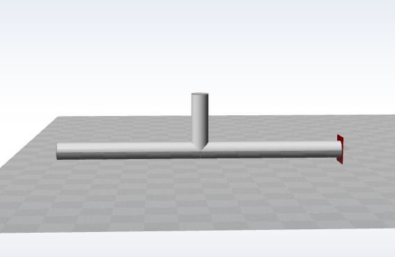
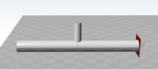
3 Test 1: T-Joint with Vertical Load
3.1 Model Configuration
The T-joint is defined with the following nodes:
| Node | X (m) | Y (m) | Z (m) |
|---|---|---|---|
| A | 0 | 0 | 0 |
| B | 10 | 0 | 0 |
| C | 5 | 0 | 2 |
| D | 5 | 0 | 0 |
The cross section is circular hollow with:
- Diameter: $$D = 0.6$$m
- Thickness: $$t = 0.03$$m
Two joint sensors are defined:
- Brace side: SCF_AS = 1.5, SCF_AC = 2, SCF_MIP = 2.5, SCF_MOP = 3
- Chord side: SCF_AS = 1, SCF_AC = 3, SCF_MIP = 2, SCF_MOP = 5
A vertical load of
$$F = 100\,000$$
N is applied downwards on node C.
The model is shown in the figure below:
3.2 Cross-Sectional Area
The cross-sectional area of the circular hollow section is:
$$A = \frac{\pi}{4}\left(D^2 - (D - 2t)^2\right) = \frac{\pi}{4}\left(0.6^2 - (0.6 - 2 \times 0.03)^2\right)$$
$$A = \frac{\pi}{4}\left(0.36 - 0.2916\right) = \frac{\pi}{4} \times 0.0684 = 0.05376 \text{ m}^2$$
3.3 Axial Stress
The load will produce a compressive stress in the member. The axial stress in the member is thus computed as:
$$\sigma_x = \frac{-F}{A} = \frac{-100\,000}{0.05376} = -1\,860\,119.05 \text{ Pa} = -1.860 \text{ MPa}$$
Since only a vertical load is applied with no moments, we have:
- $$\sigma_x = -1.860$$MPa
- $$\sigma_{my} = 0$$MPa
- $$\sigma_{mz} = 0$$MPa
3.4 Expected Stresses at Eight Points
| Point | Brace Side (MPa) | Chord Side (MPa) |
|---|---|---|
$$\sigma_0$$ |
-3.720 | -5.580 |
$$\sigma_{45}$$ |
-3.255 | -3.720 |
$$\sigma_{90}$$ |
-2.790 | -1.860 |
$$\sigma_{135}$$ |
-3.255 | -3.720 |
$$\sigma_{180}$$ |
-3.720 | -5.580 |
$$\sigma_{225}$$ |
-3.255 | -3.720 |
$$\sigma_{270}$$ |
-2.790 | -1.860 |
$$\sigma_{315}$$ |
-3.255 | -3.720 |
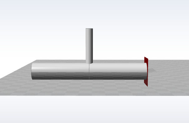
4 Test 2: Y-Joint with Different Cross Sections
4.1 Model Configuration
The Y-joint is defined with the following nodes:
| Node | X (m) | Y (m) | Z (m) |
|---|---|---|---|
| A | 0 | 0 | 0 |
| B | 8 | 0 | 0 |
| C | 4 | 0 | 3 |
| D | 4 | 0 | 0 |
The brace (member DC) has a circular hollow cross section with:
- Diameter: $$D = 0.5$$m
- Thickness: $$t = 0.025$$m
The chord (members AD and DB) has a circular hollow cross section with:
- Diameter: $$D = 1.2$$m
- Thickness: $$t = 0.04$$m
Two joint sensors are defined with the same SCFs as Test 1:
- Brace side: SCF_AS = 1.5, SCF_AC = 2, SCF_MIP = 2.5, SCF_MOP = 3
- Chord side: SCF_AS = 1, SCF_AC = 3, SCF_MIP = 2, SCF_MOP = 5
A vertical load of
$$F = 150\,000$$
N is applied downwards on node C.
The model is shown in the figure below:
4.2 Cross-Sectional Area
The cross-sectional area of the brace is:
$$A_{\text{brace}} = 0.03730 \text{ m}^2$$
4.3 Axial Stress
The axial stress in the brace is:
$$\sigma_{x,\text{brace}} = -4.021 \text{ MPa}$$
Since only a vertical load is applied with no moments, we have
$$\sigma_{my} = 0$$
and $$\sigma_{mz} = 0$$
.
4.4 Expected Stresses at Eight Points
| Point | Brace Side (MPa) | Chord Side (MPa) |
|---|---|---|
$$\sigma_0$$ |
-8.042 | -12.063 |
$$\sigma_{45}$$ |
-7.037 | -8.042 |
$$\sigma_{90}$$ |
-6.032 | -4.021 |
$$\sigma_{135}$$ |
-7.037 | -8.042 |
$$\sigma_{180}$$ |
-8.042 | -12.063 |
$$\sigma_{225}$$ |
-7.037 | -8.042 |
$$\sigma_{270}$$ |
-6.032 | -4.021 |
$$\sigma_{315}$$ |
-7.037 | -8.042 |
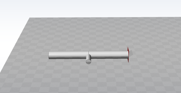
5 Test 3: T-Joint with Horizontal Load
5.1 Model Configuration
The T-joint is defined with the following nodes:
| Node | X (m) | Y (m) | Z (m) |
|---|---|---|---|
| A | 0 | 0 | 0 |
| B | 10 | 0 | 0 |
| C | 5 | 2 | 0 |
| D | 5 | 0 | 0 |
The brace (member DC) has a circular hollow cross section with:
- Diameter: $$D = 0.6$$m
- Thickness: $$t = 0.03$$m
The chord (members AD and DB) has a circular hollow cross section with:
- Diameter: $$D = 1.0$$m
- Thickness: $$t = 0.05$$m
Two joint sensors are defined:
- Brace side: SCF_AS = 1, SCF_AC = 1, SCF_MIP = 1, SCF_MOP = 4
- Chord side: SCF_AS = 1.5, SCF_AC = 1.5, SCF_MIP = 1.5, SCF_MOP = 6
A horizontal load of
$$F = 50\,000$$
N is applied in the positive x-direction on node C.
The model is shown in the figure below:
5.2 Second Moment of Area
The second moment of area of the brace circular hollow section is:
$$I = \frac{\pi}{64}\left(D^4 - (D - 2t)^4\right) = \frac{\pi}{64}\left(0.6^4 - (0.6 - 2 \times 0.03)^4\right) = 2.188\cdot 10^{-3}\text{ m}^4$$
5.3 Bending Stress
The horizontal load creates an in-plane bending moment at the joint. The moment arm is the length of the brace member DC, which is 2 m. The bending moment is:
$$M_y = F \times L = 50\,000 \times 2 = 100\,000 \text{ N·m}$$
The bending stress at the outer fiber is:
$$\sigma_{my} = \frac{M_y \times r}{I} = \frac{100\,000 \times 0.3}{0.002188} = 13.711 \text{ MPa}$$
Since only a horizontal load is applied creating an in-plane moment, we have:
- $$\sigma_x = 0$$MPa
- $$\sigma_{my} = 13.711$$MPa
- $$\sigma_{mz} = 0$$MPa
5.4 Expected Stresses at Eight Points
| Point | Brace Side (MPa) | Chord Side (MPa) |
|---|---|---|
$$\sigma_0$$ |
13.711 | 20.567 |
$$\sigma_{45}$$ |
9.695 | 14.543 |
$$\sigma_{90}$$ |
0.000 | 0.000 |
$$\sigma_{135}$$ |
-9.695 | -14.543 |
$$\sigma_{180}$$ |
-13.711 | -20.567 |
$$\sigma_{225}$$ |
-9.695 | -14.543 |
$$\sigma_{270}$$ |
0.000 | 0.000 |
$$\sigma_{315}$$ |
9.695 | 14.543 |
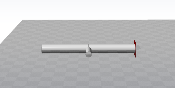
6 Test 4: T-Joint with Out-of-Plane Load
6.1 Model Configuration
The T-joint is defined with the following nodes:
| Node | X (m) | Y (m) | Z (m) |
|---|---|---|---|
| A | 0 | 0 | 0 |
| B | 10 | 0 | 0 |
| C | 5 | 2 | 0 |
| D | 5 | 0 | 0 |
The brace (member DC) has a circular hollow cross section with:
- Diameter: $$D = 0.6$$m
- Thickness: $$t = 0.03$$m
The chord (members AD and DB) has a circular hollow cross section with:
- Diameter: $$D = 1.0$$m
- Thickness: $$t = 0.05$$m
Two joint sensors are defined:
- Brace side: SCF_AS = 1, SCF_AC = 1, SCF_MIP = 3.5, SCF_MOP = 1
- Chord side: SCF_AS = 1.5, SCF_AC = 1.5, SCF_MIP = 5, SCF_MOP = 1.5
A vertical load of
$$F = 40\,000$$
N is applied upwards (positive y-direction) on node C.
The model is shown in the figure below:
6.2 Second Moment of Area
The second moment of area of the brace is:
$$I = 0.002188 \text{ m}^4$$
6.3 Bending Stress
The vertical upward load creates an out-of-plane bending moment at the joint. The moment arm is 2 m, and the bending moment is:
$$M_z = 80\,000 \text{ N·m}$$
The bending stress at the outer fiber is:
$$\sigma_{mz} = 10.97 \text{ MPa}$$
Since only an out-of-plane load is applied, we have:
- $$\sigma_x = 0$$MPa
- $$\sigma_{my} = 0$$MPa
- $$\sigma_{mz} = 10.97 $$MPa
6.4 Expected Stresses at Eight Points
| Point | Brace Side (MPa) | Chord Side (MPa) |
|---|---|---|
$$\sigma_0$$ |
0.000 | 0.000 |
$$\sigma_{45}$$ |
-7.756 | -11.63 |
$$\sigma_{90}$$ |
-10.97 | -16.45 |
$$\sigma_{135}$$ |
-7.756 | -11.63 |
$$\sigma_{180}$$ |
0.000 | 0.000 |
$$\sigma_{225}$$ |
7.756 | 11.63 |
$$\sigma_{270}$$ |
10.97 | 16.45 |
$$\sigma_{315}$$ |
7.756 | 11.63 |
7 Test 5: T-Joint with Combined Loading
7.1 Model Configuration
The T-joint is defined with the following nodes:
| Node | X (m) | Y (m) | Z (m) |
|---|---|---|---|
| A | 0 | 0 | 0 |
| B | 10 | 0 | 0 |
| C | 5 | 0 | 2 |
| D | 5 | 0 | 0 |
The brace (member DC) has a circular hollow cross section with:
- Diameter: $$D = 0.6$$m
- Thickness: $$t = 0.03$$m
The chord (members AD and DB) has a circular hollow cross section with:
- Diameter: $$D = 1.0$$m
- Thickness: $$t = 0.05$$m
Two joint sensors are defined:
- Brace side: SCF_AS = 2, SCF_AC = 4, SCF_MIP = 3, SCF_MOP = 5
- Chord side: SCF_AS = 3, SCF_AC = 6, SCF_MIP = 4, SCF_MOP = 6
A combined load is applied on node C with:
- $$F_x = 20\,000$$N
- $$F_y = 30\,000$$N
- $$F_z = -80\,000$$N
The model is shown in the figure below:
7.2 Cross-Sectional Area and Second Moment of Area
The cross-sectional area of the brace is:
$$A = 0.05372 \text{ m}^2$$
The second moment of area of the brace is:
$$I = 0.002188 \text{ m}^4$$
7.3 Axial and Bending Stresses
The axial stress from the vertical load is:
$$\sigma_x = -1.489 \text{ MPa}$$
The in-plane bending moment from the horizontal load
$$F_x$$
creates a moment $$M_y = 40\,000$$
N·m, resulting in:
$$\sigma_{my} = 5.484 \text{ MPa}$$
The out-of-plane bending moment from the horizontal load
$$F_y$$
creates a moment $$M_z = 60\,000$$
N·m, resulting in:
$$\sigma_{mz} = 8.227 \text{ MPa}$$
The combined stresses are:
- $$\sigma_x = -1.489$$MPa
- $$\sigma_{my} = 5.484$$MPa
- $$\sigma_{mz} = 8.227$$MPa
7.4 Expected Stresses at Eight Points
| Point | Brace Side (MPa) | Chord Side (MPa) |
|---|---|---|
$$\sigma_0$$ |
-19.43 | -26.41 |
$$\sigma_{45}$$ |
12.99 | 12.69 |
$$\sigma_{90}$$ |
35.18 | 40.43 |
$$\sigma_{135}$$ |
36.25 | 43.72 |
$$\sigma_{180}$$ |
13.48 | 17.47 |
$$\sigma_{225}$$ |
-21.92 | -26.09 |
$$\sigma_{270}$$ |
-47.09 | -56.30 |
$$\sigma_{315}$$ |
-45.19 | -57.12 |
8 Report
A time simulation of 5 seconds is run for each load case and the last 20% are compared to the analytical solution. If the results from Ashes are within 0.5% of the analytical solution, the test is considered passed.
The report of this test can be found on the following link: