Wind at prebent blade
This test verifies that Ashes correctly computes the wind velocity at the tip of a prebent blade. Two modified versions of the IEA 22-MW blade are used: one with a large in-plane prebend and one with a large out-of-plane prebend. A uniform wind field with a power-law shear profile is applied, so that the wind speed varies with height. By varying the blade pitch and rotor azimuth angle, the tip position changes vertically, allowing a direct check of the wind speed at the tip against the analytical shear profile.
1 Test description
The rotor is locked (bearings locked, no rotation). No tilt and no cone angle are applied. The analysis type is Loads only, meaning the blades do not deflect. Eight load cases are defined, combining two blade types (in-plane prebend and out-of-plane prebend) with two azimuth angles (0° and 90°) and two pitch angles (0° and 90°). The sensor used is the blade station at the tip of Blade 1 (station 59).
The load case parameters are summarised in the table below.
| Load case | Blade type | Azimuth [°] | Pitch [°] | Tilt [°] | Cone [°] |
|---|---|---|---|---|---|
| 1 | IEA 22-MW ip_prebend | 0 | 0 | 0 | 0 |
| 2 | IEA 22-MW ip_prebend | 0 | 90 | 0 | 0 |
| 3 | IEA 22-MW ip_prebend | 90 | 0 | 0 | 0 |
| 4 | IEA 22-MW ip_prebend | 90 | 90 | 0 | 0 |
| 5 | IEA 22-MW oop_prebend | 0 | 0 | 0 | 0 |
| 6 | IEA 22-MW oop_prebend | 0 | 90 | 0 | 0 |
| 7 | IEA 22-MW oop_prebend | 90 | 0 | 0 | 0 |
| 8 | IEA 22-MW oop_prebend | 90 | 90 | 0 | 0 |
2 Model parameters
The key model parameters are:
- Hub-height wind speed: $$U_\text{hub} = 10.0 \text{ m/s}$$
- Hub height: $$z_\text{hub} = 152.4 \text{ m}$$
- Wind shear exponent: $$\alpha = 0.2$$
- Hub (azimuth axis) position: $$(0.0,\ 5.0,\ 152.4) \text{ m}$$
- Pitch point position (at azimuth 0°): $$(0.0,\ 5.0,\ 153.15) \text{ m}$$
- Initial tip position, in-plane prebend blade (azimuth 0°, pitch 0°): $$(1.0,\ 5.0,\ 291.9) \text{ m}$$
- Initial tip position, out-of-plane prebend blade (azimuth 0°, pitch 0°): $$(0.0,\ 75.0,\ 291.9) \text{ m}$$
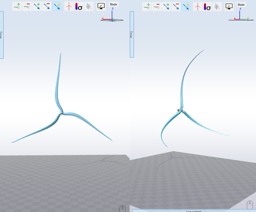
The model used for this test is illustrated in the figure below at 0 azimuth and 0 pitch, for the in-plane blade (left) and the out-of-plane blade (right).
3 Analytical solution
The wind speed follows a power-law shear profile:
$$U(z) = U_\text{hub} \left(\frac{z}{z_\text{hub}}\right)^{\alpha}$$
where
$$z$$
is the height of the point of interest,
$$U_\text{hub}$$
is the wind speed at hub height,
$$z_\text{hub}$$
is the hub height, and
$$\alpha$$
is the shear exponent.
The tip position for each load case is obtained by applying the azimuth rotation (about the hub axis, along
$$-y$$
) and the pitch rotation (about the pitch axis, along $$-z$$
at azimuth 0°) to the initial tip position. The height coordinate $$z$$
of the rotated tip is then used to evaluate the wind speed from the shear profile above.
The expected tip positions and corresponding wind speeds for each load case are given in the table below.
| Load case | Blade type | Tip x [m] | Tip y [m] | Tip z [m] | Expected wind speed [m/s] |
|---|---|---|---|---|---|
| 1 | ip_prebend | 1.0 | 5.0 | 291.9 | 11.388 |
| 2 | ip_prebend | 0.0 | 4.0 | 291.9 | 11.388 |
| 3 | ip_prebend | -139.5 | 5.0 | 153.4 | 10.013 |
| 4 | ip_prebend | -139.5 | 4.0 | 152.4 | 10.000 |
| 5 | oop_prebend | 0.0 | 75.0 | 291.9 | 11.388 |
| 6 | oop_prebend | 70.0 | 5.0 | 291.9 | 11.388 |
| 7 | oop_prebend | -139.5 | 75.0 | 152.4 | 10.000 |
| 8 | oop_prebend | -139.5 | 5.0 | 222.4 | 10.785 |
4 Results
A test is considered passed when all values of the last second of the results produced by Ashes are within 0.01% of the analytical solution.
The report for this test can be found at the following link:
https://www.simis.io/downloads/open/benchmarks/current/WindAtPreBentBlade.pdf
https://www.simis.io/downloads/open/benchmarks/current/WindAtPreBentBlade.pdf