Material nonlinearity and plastic hinges
1 Overview
By default, the
FEM code in Ashes treats the structure as
linear elastic: stresses are proportional to strains and the material never yields, no matter how large the load. For many wind-turbine load cases this is sufficient, because the design intent is precisely to keep the structure in its elastic range. To study the structural response
beyond yield — overload events, accidental loads, pushover analyses, or the energy a member can dissipate during extreme cyclic loading — Ashes provides a
material-nonlinear beam element based on
concentrated plastic hinges.
The nonlinearity is introduced through a dedicated element type that combines an elastic
Euler-Bernoulli beam with a
nonlinear moment–rotation law concentrated at the two element ends. The constitutive law is the
Giuffré–Menegotto–Pinto (GMP) model with isotropic strain hardening, the same smooth elastoplastic law popularised by the OpenSees
Steel02 material. Only the
bending response is made nonlinear; the
axial and torsional responses remain linear elastic.
It helps to keep
two distinct ideas separate, because they answer two different questions and are described in two different sections of this page:
- How is the material treated? — the stress–strain law that describes how the steel itself behaves once it yields: how stress responds to strain, what happens on unloading, and how it hardens under repeated cycles. This is a property of the material alone, independent of any particular beam, and is covered in Section 3.
- How is the element treated? — how that material behaviour is assembled into the force–deformation response of a beam. Ashes does this by concentrating all the yielding into plastic hinges at the element ends, leaving the interior elastic. This is covered in Section 2.
In short: one layer is “what does the steel do”, the other is “how is that steel arranged into a beam that bends”. The two are connected by the
moment–rotation mapping of Section 2.2: rather than applying the stress–strain law at every point of the cross section, Ashes reuses the
same material law one level up to describe each hinge’s moment–rotation behaviour. The material law therefore does double duty, which is efficient but slightly blurs the separation between the two layers.
Note: Material nonlinearity in Ashes is a lumped-plasticity (plastic-hinge) formulation, not a distributed-plasticity / fibre-section formulation. All inelastic deformation is concentrated at the element ends; the interior of each element stays elastic. To capture a plastic zone of finite length, discretise that region with several elements so that hinges can form at successive nodes.
2 The plastic-hinge beam element
The nonlinear element is an Euler-Bernoulli beam carrying a
plastic hinge at each end and for
each of the two bending axes — four hinges in total per element. A hinge is a zero-length rotational spring whose moment–rotation response follows the GMP law described in Section 3. While a hinge is elastic it is rigid (it adds no flexibility) and the element behaves as an ordinary elastic beam; once the end moment approaches the yield moment, the hinge softens and concentrates the inelastic rotation.
2.1 Yield moment
Each hinge yields when the end moment reaches the
plastic yield moment of the cross section. For bending about a principal axis this is the material yield stress
$$\sigma_y$$
times the
plastic section modulus
$$Z$$
of the section about that axis:
$$M_{y,1}=\sigma_y\,Z_1\qquad M_{y,2}=\sigma_y\,Z_2$$
where the subscripts 1 and 2 denote the two principal bending axes of the cross section. Using the
plastic (rather than elastic) section modulus means the yield moment corresponds to a fully plastified section, consistent with the lumped-hinge idealisation.
Note: The plastic section modulus
$$Z$$
is a purely geometric property of the cross-section's shape. It should not be confused with the more familiar elastic section modulus $$S=I/c$$
(with $$I$$
the second moment of area and $$c$$
the distance to the extreme fibre). The elastic modulus gives the moment at first yield, when only the outermost fibre has just reached the yield stress; the plastic modulus gives the moment at full plastification, when every fibre across the section has reached the yield stress (tension on one side, compression on the other) — the idealised plastic-hinge state. Geometrically $$Z$$
is the first moment of the two halves of the area about the axis that splits the area in two, and it is always larger than $$S$$
.
Ashes computes the plastic section modulus analytically from the section geometry. The expressions used for each supported cross-section type are:
-
for
Circular hollow sections (outer radius
$$R_o$$, inner radius$$R_i$$), the same value about both axes:$$Z=\tfrac{4}{3}\left(R_o^{3}-R_i^{3}\right)$$
-
for
Circular solid sections (radius
$$r$$), the same value about both axes:$$Z=\tfrac{4}{3}r^{3}$$
-
for
Rectangular solid sections, with side lengths
$$b$$and$$h$$along the two principal axes, the modulus for bending about an axis uses the dimension perpendicular to that axis as the squared term:$$Z=\tfrac{b\,h^{2}}{4}$$
Note: A plastic section modulus is only available for cross sections defined by their geometry (Circular hollow, Circular solid, Rectangular solid). Cross sections defined only by their structural properties (such as the generic Circular shape and Rectangular shape sections) do not provide one, so they cannot be used with plastic hinges — a nonlinear member must be assigned a geometry-defined cross section.
2.2 Moment–rotation mapping
The GMP law is written in a generic stress–strain form (Section 3). The element reuses that same law for its moment–rotation hinge by mapping moment onto “stress” and a chord-rotation measure onto “strain”. With the element bending stiffness
$$EI$$
and length
$$L$$
, a reference rotational stiffness is defined as
$$k_{\text{ref}}=\frac{EI}{L}$$
and the GMP material is evaluated with the substitutions
$$\sigma \rightarrow M,\qquad \varepsilon \rightarrow \frac{M}{k_{\text{ref}}},\qquad E \rightarrow k_{\text{ref}},\qquad \sigma_y \rightarrow M_y$$
where, on the left of each arrow is the quantity that appears in the generic material law of Section 3 and, on the right, the rotational quantity it stands for at the hinge:
-
$$\sigma$$— the material stress, here standing for the bending moment$$M$$at the hinge (the end of the element);
-
$$\varepsilon$$— the material strain, here standing for a chord-rotation measure$$M/k_{\text{ref}}$$, i.e. the rotation that the reference stiffness would produce under the moment$$M$$;
-
$$E$$— the material elastic (Young's) modulus, here standing for the reference rotational stiffness$$k_{\text{ref}}=EI/L$$defined above;
-
$$\sigma_y$$— the material yield stress, here standing for the yield moment$$M_y=\sigma_y Z$$of the cross section (Section 2.1).
so that a call to the material law returns the hinge moment and its tangent rotational stiffness. This keeps a single, well-tested constitutive routine for both interpretations.
2.3 Element stiffness (Giberson hinge)
For each bending axis, the two end rotations
$$[\theta_i,\ \theta_j]$$
are related to the two end moments
$$[M_i,\ M_j]$$
through a
Giberson one-component model: the elastic flexibility of the beam in series with a zero-length plastic hinge at each end. The total flexibility is
$$\mathbf{f}_{\text{total}}=\mathbf{f}_{\text{beam}}+\operatorname{diag}\!\left(f_{h,i},\ f_{h,j}\right),\qquad \mathbf{f}_{\text{beam}}=\frac{L}{6EI}\begin{bmatrix} 2 & -1 \\ -1 & 2 \end{bmatrix}$$
where the elastic part
$$\mathbf{f}_{\text{beam}}$$
is the standard Euler-Bernoulli end-rotation flexibility, and each hinge contributes
$$f_{h}=\max\!\left(0,\ \frac{1}{E_{\text{tan}}}-\frac{1}{k_{\text{ref}}}\right)$$
with
$$E_{\text{tan}}$$
the current tangent stiffness of that hinge. The
$$\max(0,\cdot)$$
clamp means that an elastic hinge (
$$E_{\text{tan}}=k_{\text{ref}}$$
) adds no flexibility and the matrix collapses back to the pure elastic beam. The end-rotation stiffness is the inverse
$$\mathbf{K}=\mathbf{f}_{\text{total}}^{-1}$$
, so the end moments follow from the end rotations as
$$[M_i,\ M_j]^{\top}=\mathbf{K}\,[\theta_i,\ \theta_j]^{\top}$$
. While both hinges are elastic (
$$f_h=0$$
) this is just
$$\mathbf{f}_{\text{beam}}^{-1}$$
, recovering the standard Euler-Bernoulli end-moment relations
$$M_i=\tfrac{4EI}{L}\theta_i+\tfrac{2EI}{L}\theta_j$$
(and symmetrically for
$$M_j$$
) — this elastic case is the elastic-trial moment used by the solution algorithm of Section 4. Because the two hinges are added independently, the element correctly represents the
asymmetric case where only one end has yielded: that end softens while the other retains its elastic stiffness.3 The Giuffré–Menegotto–Pinto material law
The hinge constitutive law is the smooth elastoplastic curve of Menegotto & Pinto (1973) with the isotropic strain-hardening extension of Filippou, Popov & Bertero (1983). Compared with a simple bilinear law, the GMP curve replaces the sharp corner at yield with a
smooth, continuously curving transition between the elastic and post-yield branches, which both reproduces the real rounded response of structural steel and avoids the numerical kink of a bilinear model. The default parameters reproduce the OpenSees
Steel02 material.
3.1 Smooth stress–strain curve
The curve is expressed in
normalized coordinates measured from the last load-reversal point. Let
$$(\varepsilon_R,\sigma_R)$$
be the strain–stress state at the last reversal and
$$(\varepsilon_0,\sigma_0)$$
the intersection of the elastic and post-yield asymptotes for the current branch. The normalized strain and stress are
$$\varepsilon^{*}=\frac{\varepsilon-\varepsilon_R}{\varepsilon_0-\varepsilon_R},\qquad \sigma=\sigma_R+\sigma^{*}\,(\sigma_0-\sigma_R)$$
and the GMP law gives the normalized stress as a function of normalized strain:
$$\sigma^{*}=b\,\varepsilon^{*}+\frac{(1-b)\,\varepsilon^{*}}{\left(1+\left|\varepsilon^{*}\right|^{R}\right)^{1/R}}$$
Here
$$b=E_t/E$$
is the
post-yield slope ratio (the ratio of the hardening tangent to the elastic modulus), and
$$R$$
is a
curvature parameter controlling the sharpness of the transition. A large
$$R$$
produces a sharp, almost bilinear corner; in the limit
$$R\rightarrow\infty$$
the curve collapses exactly to the bilinear law, while a small
$$R$$
gives a very rounded knee. The asymptote intersection is found by intersecting the elastic-slope line through the reversal point with the post-yield line of slope
$$bE$$
through the (possibly hardened) yield point
$$(\pm\varepsilon_{y,\text{iso}},\ \pm\sigma_{y,\text{iso}})$$
:
$$\varepsilon_0=\pm\,\varepsilon_{y,\text{iso}}+\frac{E\,\varepsilon_R-\sigma_R}{E\,(1-b)},\qquad \sigma_0=\sigma_R+E\,(\varepsilon_0-\varepsilon_R)$$
with the sign chosen according to the loading direction of the new branch. The tangent modulus follows by differentiation:
$$E_{\text{tan}}=\left[b+\frac{1-b}{\left(1+\left|\varepsilon^{*}\right|^{R}\right)^{1+1/R}}\right]\frac{\sigma_0-\sigma_R}{\varepsilon_0-\varepsilon_R}$$
3.2 Load reversals and curvature softening
A
reversal is detected whenever the strain rate changes sign relative to the current branch. At a reversal the model stores the current point as the new anchor
$$(\varepsilon_R,\sigma_R)$$
, switches branch direction, and recomputes the asymptote intersection. This is what gives the model its
Bauschinger-like hysteresis: unloading follows the elastic slope and reloading curves smoothly toward the opposite asymptote.
The curvature parameter is not constant. It
softens with cumulative plastic deformation, so the knee of the curve becomes rounder as the material accumulates damage over many cycles. At each reversal
$$R$$
is updated from its initial value
$$R_0$$
as
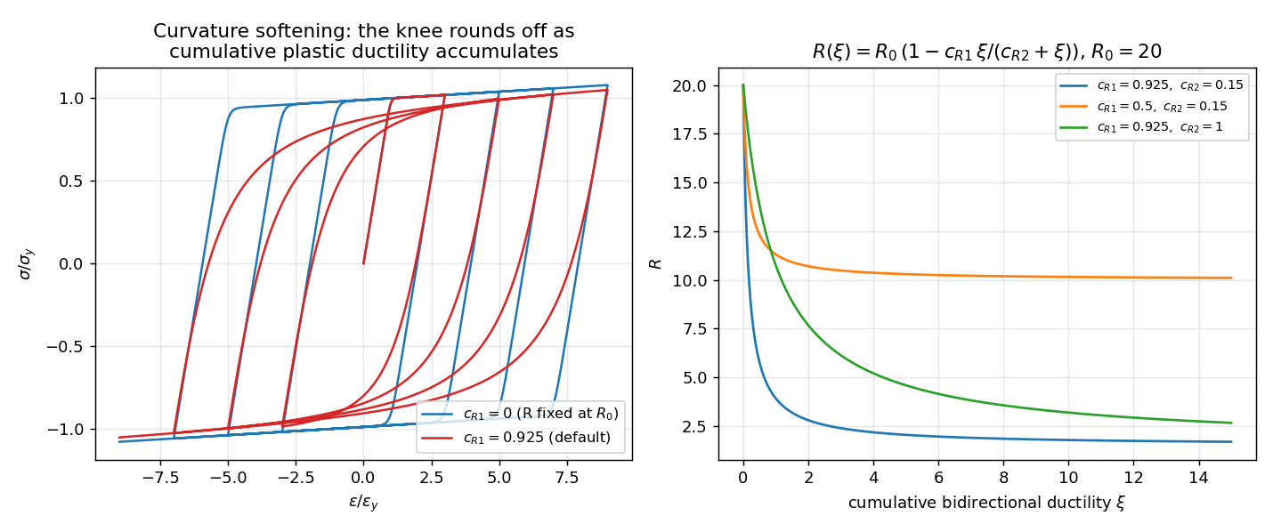
$$R=R_0\left(1-\frac{c_{R1}\,\xi}{c_{R2}+\xi}\right),\qquad \xi=\frac{\varepsilon_{p,\max}^{+}+\left|\varepsilon_{p,\max}^{-}\right|}{(1-b)\,\varepsilon_y}$$
where
$$\xi$$
is the
cumulative bidirectional plastic ductility — the sum of the largest tensile and compressive plastic excursions, each normalized by the yield strain
$$\varepsilon_y=\sigma_y/E$$
. The constants
$$c_{R1}$$
and
$$c_{R2}$$
shape how quickly the transition rounds off with damage; the value of
$$R$$
is held fixed over each branch and is floored at a small positive value for numerical stability.3.3 Isotropic hardening
In addition to the kinematic-like response built into the reversal logic, the yield surface can
expand with accumulated plastic strain (isotropic hardening). The effective yield stress grows with the largest plastic excursion seen in that direction:
$$\sigma_{y,\text{iso}}=\sigma_y\left[1+a_1\,\max\!\left(\frac{\left|\varepsilon_{p,\max}\right|}{\varepsilon_y}-a_2,\ 0\right)\right]$$
The coefficient
$$a_1$$
scales the amount of isotropic hardening and
$$a_2$$
sets the plastic-ductility threshold (in multiples of the yield strain) below which no isotropic hardening occurs. The expansion is tracked
independently in tension and compression, so after the first plastic half-cycle the yield radius can differ between the two directions. Setting
$$a_1=0$$
disables isotropic hardening entirely, leaving only the post-yield slope
$$b$$
as the source of hardening.4 Solution algorithm
This section collects the theory of the previous sections into the sequence the model actually follows. It is written at the
theory level: a single pass through the constitutive law and element assembly. In a real simulation these steps are repeated several times within each time step as the equilibrium iteration converges — that outer loop is described in
Section 6 and is omitted here for clarity.
Once, when the model is built:
-
Compute each hinge’s
yield moment
$$M_y=\sigma_y Z$$from the material yield stress and the cross-section’s plastic section modulus (Section 2.1), and initialise each hinge as undeformed, with curvature parameter at its initial value$$R_0$$.
At a given deformation state, for each hinge:
-
Map rotation to the material law (Section 2.2): form the elastic-trial moment from the current end rotations (the elastic end moment of Section 2.3), divide by the reference stiffness
$$k_{\text{ref}}=EI/L$$to obtain the “strain” input, and use$$M_y$$as the yield level. From here the hinge is treated as a one-dimensional stress–strain point.
- Detect a reversal (Section 3.2): has the strain rate changed sign relative to the current branch?
-
If a new branch begins (first loading or a reversal), rebuild the curve:
-
anchor the reversal point
$$(\varepsilon_R,\sigma_R)$$;
- update the largest plastic excursion in the direction just left (tensile or compressive);
-
expand the yield level by isotropic hardening to
$$\sigma_{y,\text{iso}}$$(Section 3.3; no change when$$a_1=0$$);
-
intersect the elastic and post-yield asymptote lines to locate the corner
$$(\varepsilon_0,\sigma_0)$$(Section 3.1);
-
soften the curvature
$$R$$from the accumulated bidirectional ductility$$\xi$$(Section 3.2).
-
anchor the reversal point
-
Evaluate the GMP curve at the current normalized strain (Section 3.1) and de-normalize to get the
resisting moment
$$M$$the hinge carries at this deformation.
-
Take the
tangent stiffness
$$\mathrm{d}M/\mathrm{d}\theta$$, the local slope of that curve at the current point (Section 2.2).
-
Update the hinge’s
plastic bookkeeping: the plastic part of the deformation
$$\varepsilon_p=\varepsilon-\sigma/E$$, the accumulated plastic excursion, and the dissipated hysteretic energy.
Assembling the element response (Section 2.3):
-
Turn each end’s tangent stiffness into a rotational
hinge flexibility
$$f_h=\max\!\left(0,\ 1/E_{\text{tan}}-1/k_{\text{ref}}\right)$$(zero while the hinge is elastic), add it to the elastic beam flexibility, and invert the result to the 2×2 end-rotation stiffness — so the two ends soften independently.
- Return the bending response (resisting moments and this stiffness) for the axis; the axial and torsional responses are added unchanged as linear elastic.
Over the whole simulation:
-
The load is advanced and the steps above repeat. Each hinge
carries its history forward — reversal point, peak plastic excursions, accumulated damage, softened
$$R$$and hardened yield level. This is what makes the response path-dependent: the same rotation produces a different moment depending on what the hinge has already been through.
5 Material parameters and usage
A nonlinear material is defined by the elastic properties shared by every Ashes material — Young's modulus
$$E$$
, Poisson's ratio
$$\nu$$
, density
$$\rho$$
and yield stress
$$\sigma_y$$
— plus the six GMP parameters described above:-
Post-yield ratio
$$b$$— ratio of post-yield to elastic stiffness. Default$$b=0.015$$. Use$$b=0$$for a perfectly plastic material; values approaching 1 suppress yielding.
-
Initial curvature
$$R_0$$— sharpness of the elastic–plastic transition. Default$$R_0=20$$.
-
Transition constants
$$c_{R1},\ c_{R2}$$— control how the curvature softens with cumulative damage. Defaults$$c_{R1}=0.925,\ c_{R2}=0.15$$.
-
Isotropic-hardening parameters
$$a_1,\ a_2$$— amount and threshold of yield-surface expansion. Defaults$$a_1=0$$(no isotropic hardening) and$$a_2=1$$.
The default set
$$(R_0,c_{R1},c_{R2},a_1,a_2)=(20,\,0.925,\,0.15,\,0,\,1)$$
matches the recommended OpenSees
Steel02 values, so a material defined with only
$$E,\ \sigma_y$$
and
$$b$$
already behaves like a standard Steel02 curve.
In an Ashes structural input (text) file, a nonlinear material is declared with the
BilinearGMP keyword in the materials block, following the pattern
name E nu density yieldStress BilinearGMP b R0 cR1 cR2 a1 a2
for example a structural steel with
$$E=2.1\cdot10^{11}\text{ Pa}$$
,
$$\sigma_y=2.5\cdot10^{8}\text{ Pa}$$
and
$$b=0.015$$
reads as nlsteel 2.1e11 0.3 7850 2.5e8 BilinearGMP 0.015 18 0.9 0.15 0.0 1.0. Members assigned a BilinearGMP material are meshed with plastic-hinge beam elements automatically.6 Stress update and solution
The element participates in the standard nonlinear time-domain solution. Within each Newton-Raphson iteration of a time step, every hinge runs the GMP update as a
trial state computed from the committed (last converged) history: an elastic moment predictor is formed from the current end rotations, the GMP law returns the corrected hinge moment and tangent stiffness, and the internal forces and tangent stiffness matrix are updated accordingly. The committed history is only overwritten once the step
converges; if the step is rejected the trial state is discarded, so the path-dependent history (reversal points, plastic excursions, accumulated damage) stays consistent.
To keep the iteration well-conditioned across the smooth GMP knee, the stiffness handed to the solver blends the local tangent with a secant measure and is bounded between the post-yield ratio
$$b$$
and the full elastic stiffness. This prevents stiffness from swinging too abruptly during monotonic loading while preserving the elastic stiffness on unloading branches.
Alongside the moments and stresses, each hinge reports diagnostics that are exposed through the beam-element sensors: whether the hinge has yielded, the
accumulated plastic rotation, the effective (hardened) yield moment, the number of load reversals, and the
dissipated hysteretic energy
$$\textstyle\int \left|M\,\mathrm{d}\theta_p\right|$$
accumulated over the simulation. The dissipated energy is the area of the hysteresis loops and is the natural measure of how much inelastic work a member has absorbed.Note: The Ashes plastic-hinge implementation is validated against OpenSees in the structural benchmark tests (static pushover, dynamic cantilever, and cyclic/sinusoidal load cases), where the GMP moment–rotation response and hysteresis loops are compared directly with the equivalent Steel02 model.
7 Sensor outputs for nonlinear members
A member with a nonlinear (BilinearGMP) material exposes a set of
plastic-hinge diagnostic fields through its beam-element sensor, in addition to the usual forces, moments and displacements. These fields report the inelastic state of the hinges described in the previous sections. They are
specific to nonlinear members: they are enabled automatically when the element uses a nonlinear material and read zero on ordinary linear-elastic beams.
Most of these quantities are reported
per hinge, so each one appears as four fields. The field-name suffixes identify which hinge:
- (1st prin.) / (2nd prin.) — bending about the cross section’s 1st or 2nd principal axis;
- , i / , j — the hinge at the element’s first or second end.
The only exception is the dissipated energy, which is a single value summed over the whole element. The table below lists one entry per family (the suffixes are omitted):
| Field | Unit | Represents |
| Plastic rotation | rad | Signed plastic hinge rotation θp — the inelastic (non-recoverable) part of the end rotation at the current state. Zero while the hinge is elastic. |
| Accum. plastic rotation | rad | Cumulative plastic rotation: the running sum of the magnitudes of all plastic-rotation increments. Only ever increases — a measure of total accumulated inelastic demand at the hinge. |
| Hinge yielded | – | Flag (0 or 1): 1 once the accumulated plastic rotation exceeds 1% of the yield rotation My/kref. The small threshold filters the tiny plastic rotation the smooth GMP curve produces just below yield, so the flag marks genuine yielding. |
| Effective yield moment | N·m | The current yield moment after isotropic hardening, My,iso. Equal to the base yield moment My = σyZ when isotropic hardening is off (a1 = 0); grows once the hinge has yielded when a1 > 0 (Section 3.3). |
| Moment / yield ratio | – | Utilisation ratio |M| / My,iso at the hinge. Below 1 the hinge is essentially elastic; at or above 1 it is at or beyond yield. A convenient single number for how hard a hinge is working. |
| Reversal count | – | Number of load-direction reversals the hinge has undergone — i.e. how many half-cycles of cyclic plastic action it has seen (Section 3.2). |
| Dissipated energy (sum) | J | Total hysteretic energy ∫|M dθp| dissipated by plastic flow, summed over all four hinges of the element — the area enclosed by the moment–rotation hysteresis loops. A single value per element, not per hinge. |
Note: Counting all variants, this adds 25 fields: six per-hinge families × four hinges (two ends × two principal axes) = 24, plus the single element-level dissipated energy.
8 Illustrative GMP curves
The figures in this section illustrate the behaviour described analytically in Sections 3 and 4. They were produced by a standalone reimplementation of the documented GMP equations, driven by prescribed strain (or rotation) histories. All axes are normalised by the yield point — stress by σy and strain by εy — so the same curves apply directly to a plastic hinge under the moment–rotation mapping of Section 2.2 (simply relabel the axes M/My and θ/θy, with E → kref = EI/L and σy → My).
8.1 Monotonic response: effect of R0 and b
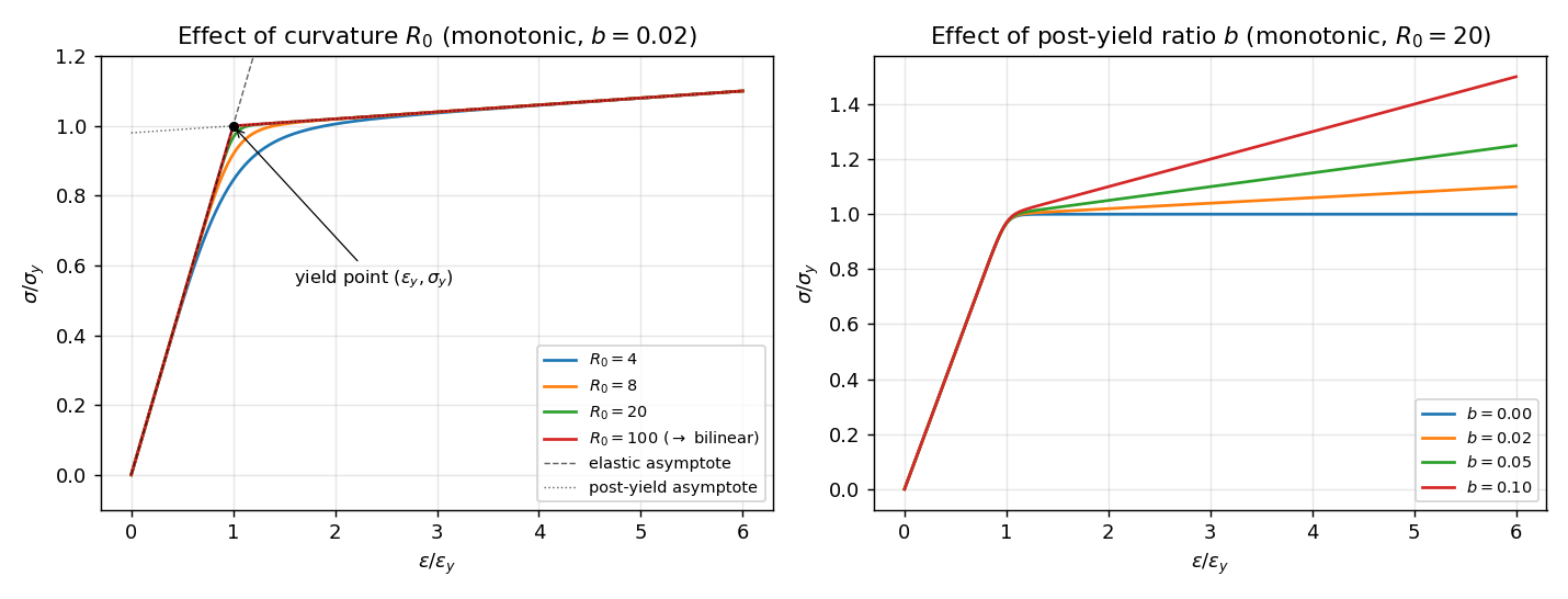
These two plots show the monotonic (first-loading) response, sweeping the two parameters that shape the curve. On the left, the curvature parameter R0 is varied at fixed b: a small R0 gives a very rounded knee, while a large R0 sharpens it — by R0 = 100 the curve is already almost indistinguishable from the bilinear law. The dashed line is the elastic asymptote (slope E, through the origin) and the dotted line the post-yield asymptote (slope bE, through the yield point); on first loading from the origin these two lines intersect exactly at the yield point, so here the corner (ε0, σ0) and the yield point (εy, σy) coincide (marked). The two separate only after a load reversal, when the elastic asymptote shifts to pass through the new reversal anchor — as in Figure 8.2. On the right, the post-yield ratio b is varied at fixed R0: b sets the slope of the hardening branch, from b = 0 (perfectly plastic, flat plateau) to progressively stiffer hardening.
8.2 A single load reversal
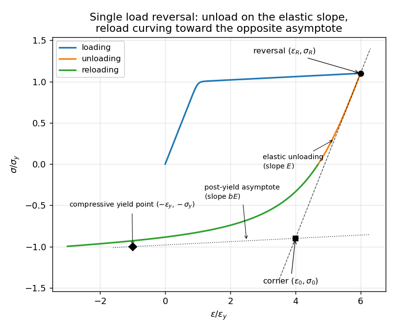
This figure isolates one load reversal to show the construction of Sections 3.1–3.2. The material is loaded well past yield (to 6 εy), then unloaded and reloaded in compression. Unloading leaves the curved loading branch and follows the steep elastic slope E from the reversal anchor (εR, σR); the reload then curves smoothly toward the opposite post-yield asymptote. The corner (ε0, σ0) is the intersection of the elastic line through the reversal point with the post-yield line, recomputed for the new branch. That post-yield line is the hardening (plastic) asymptote: it has slope bE and is drawn through the yield point in the new loading direction — here the compressive yield point (−εy, −σy), or the isotropically expanded point (−εy,iso, −σy,iso) when hardening is active. The unloading and reloading are drawn in different colours, but they are two phases of a single GMP branch — one reversal anchor, one corner. This rounded unload–reload — rather than a retracing of the loading path — is the Bauschinger-like behaviour that produces the hysteresis loops. Note how much rounder this corner is than the first-loading knee of Figure 8.1: at the reversal the curvature parameter has softened from R0 = 20 to roughly R ≈ 2 (Section 3.2), which is what blunts the knee.
8.3 Isotropic hardening
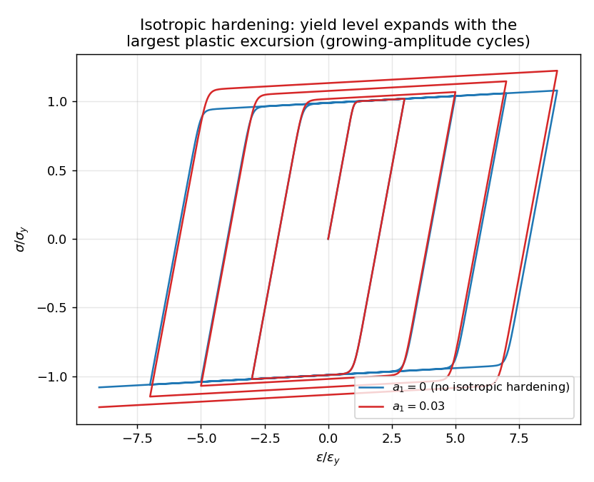
Growing-amplitude cycles with isotropic hardening off (a1 = 0, blue) and on (a1 = 0.03, red). With a1 = 0 the peak stress saturates near σy on every cycle — the only hardening is the gentle post-yield slope b. With a1 > 0 the yield level expands with the largest plastic excursion seen in each direction (Section 3.3), so successive peaks climb higher and the loops grow outward. Curvature softening is switched off here (cR1 = 0) so the hardening effect is seen in isolation.
8.4 Curvature softening
Left: the same growing-amplitude cycles with curvature softening off (cR1 = 0, blue — knees stay as sharp as R0 dictates) and at the default cR1 = 0.925 (red — the knees become progressively rounder as cumulative plastic ductility accumulates). Isotropic hardening is disabled (a1 = 0) to isolate the softening. Right: the softening law R(ξ) = R0(1 − cR1ξ/(cR2 + ξ)) itself, for a few parameter pairs, where ξ is the cumulative bidirectional plastic ductility of Section 3.2. cR1 controls how far R falls and cR2 how quickly.
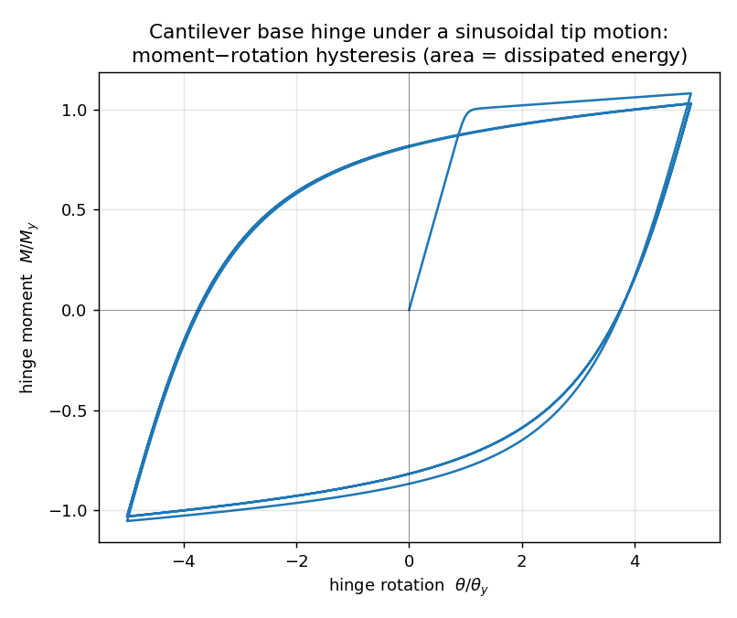
8.5 Cyclic hysteresis loop
A constant-amplitude sinusoidal tip motion applied to a cantilever with a single nonlinear element, plotted as the base-hinge moment against its rotation — the Section 2.2 moment–rotation reading of the law (M/My versus θ/θy). The base hinge carries the largest moment, so it is where the plasticity concentrates. After the first quarter-cycle the loop is stable and closed; the area it encloses is the dissipated hysteretic energy ∫|M dθp| reported by the element’s Dissipated energy sensor (Section 7). This moment–rotation loop is the natural way to visualise a member’s cyclic energy dissipation; plotting tip load against tip displacement gives a similar loop, but tilted by the elastic flexibility of the member.