Opensees nonlinear material ten elements sinusoidal geometric nonlinear
1 Test description
This test verifies the dynamic response of Ashes' nonlinear (elasto-plastic) beam elements when both material and geometric nonlinearity are active. A tubular cantilever tower is meshed into ten PlasticHinge elements with a BilinearGMP (Giuffré-Menegotto-Pinto, “Steel02”) material, a horizontal sinusoidal point force is applied at the tip (RNA) node, and the resulting tip displacement is benchmarked against an independent OpenSees reference solution.
It is the large-displacement companion to the small-displacement sibling
Opensees nonlinear material ten elements sinusoidal. The key difference is that here the Ashes analysis mode is set to Nonlinear, so the geometrically nonlinear (corotational) formulation is used and P-Delta / large-displacement effects are captured. Under the plastic load cases the tip swings to roughly 2 m on a 10 m cantilever — about 20% of the tower height — a regime where the small-displacement assumption is no longer valid and geometric nonlinearity must be accounted for.
Four load cases combine two amplitudes — one in the elastic range and one well into the plastic range (the yield tip force is
$$F_y\approx594\text{ kN}$$
) — with two periods, to exercise both reversible response and hysteretic cycling:-
Load case 1:
$$F_{amp}=400\text{ kN},\; T=10\text{ s}$$(elastic, slow)
-
Load case 2:
$$F_{amp}=400\text{ kN},\; T=4\text{ s}$$(elastic, faster)
-
Load case 3:
$$F_{amp}=800\text{ kN},\; T=10\text{ s}$$(plastic, slow)
-
Load case 4:
$$F_{amp}=800\text{ kN},\; T=4\text{ s}$$(plastic, faster)
All four cases use mass-proportional Rayleigh damping set to roughly 2% of critical at the first cantilever mode (see Section 2). The point of refining the mesh to ten elements is to exercise the spread of plasticity along the tower height: under the 800 kN cases the bending moment exceeds the yield moment over the bottom portion of the tower, so yielding is distributed over several elements rather than lumped in one.
2 Model
The Ashes model is a single tubular tower modelled with the
Tubular tower only template. The structural member is divided into ten PlasticHinge beam elements of 1 m each, using the support-section input file Ten_element_GMP.txt (identical to the small-displacement sibling).
Geometry — a 10 m vertical cantilever, fixed at the base, with a circular hollow cross-section:
$$H=10\text{ m},\quad D=1\text{ m},\quad t=25\text{ mm}$$
Material (BilinearGMP / Steel02):
$$E=2.1\cdot10^{11}\text{ Pa},\quad \nu=0.3,\quad f_y=2.5\cdot10^{8}\text{ Pa},\quad b=0.015$$
with GMP transition parameters
$$R_0=18,\; c_{R1}=0.9,\; c_{R2}=0.15$$
and no isotropic hardening
$$(a_1=0,\; a_2=1)$$
.
A 100 t RNA point mass is placed at the tip node; the tower's own steel mass (~6 t) is negligible by comparison, and the rotational inertia is zero. The derived section and structural quantities are:
$$Z_p=\tfrac{4}{3}\left(R_o^3-R_i^3\right)\approx0.0238\text{ m}^3,\quad M_y=f_y Z_p\approx5.94\text{ MN·m},\quad EI\approx1.91\text{ GN·m}^2$$
$$k=\frac{3EI}{H^3}\approx5.74\text{ MN/m},\quad F_y=\frac{M_y}{H}\approx594\text{ kN},\quad \delta_y=\frac{F_y}{k}\approx0.104\text{ m},\quad T_n\approx0.83\text{ s}$$
The load is a prescribed Force at the tip (RNA) node along the x-axis. Each load case sets the amplitude and a non-zero “Period”, which turns the otherwise constant prescribed load into a sinusoidal one. A 2 s linear ramp-up is applied to the load (Model.RampUpScheme = Duration, RampUpDuration = 2 s, Linear), so the applied force is
$$F(t)=F_{amp}\,\mathrm{ramp}(t)\,\sin\!\left(\frac{2\pi t}{T}\right)$$
Solver settings: FemDynamic time simulation, total duration 45 s, timestep
$$\Delta t=0.001\text{ s}$$
, with FemDynamic.AnalysisMode = Nonlinear. This activates the geometrically nonlinear (corotational) beam formulation, so large displacements and P-Delta effects are captured — the defining feature of this test.
Damping is mass-proportional Rayleigh damping, specified as an explicit coefficient
$$\alpha_M=0.303\text{ rad/s}$$
, which corresponds to about 2% of critical damping at the first linear-elastic cantilever mode
$$(\omega_1=\sqrt{k/m_{tip}}\approx7.57\text{ rad/s})$$
.Note: with only light damping and load reversals that push past yield, the plastic response does not decay to zero — it accumulates and settles into a stabilized symmetric plastic cycle (ratcheting). The amplitude and shape of that stabilized cycle, now including the geometric-nonlinearity correction to the displacement, is what is compared against the reference.
3 Benchmarked solution
The reference solution is computed with OpenSees 3.7.1. The OpenSees model is a 2D cantilever (ndm 2, ndf 3), 10 m tall, fixed at the base, meshed into ten displacement-based dispBeamColumn elements with 5 Gauss integration points each, mirroring Ashes' displacement-based ten-element discretization.
Crucially, the geometric transformation is set to geomTransf Corotational, so the OpenSees formulation accounts for the same large-displacement / P-Delta effects as the Ashes Nonlinear analysis mode. Each element uses a bilinear GMP moment-curvature section built with Steel02 as the bending law, aggregated with an elastic axial response. The Steel02 parameters are mapped to the section moment-curvature law as
$$F_{y}^{\,eq}=M_y,\qquad E_0^{\,eq}=EI,\qquad b,\;R_0,\;c_{R1},\;c_{R2}\;\text{as in Ashes}$$
The same ramped sinusoidal tip force, 100 t tip mass and mass-proportional Rayleigh damping
$$(\alpha_M=0.303\text{ rad/s})$$
are applied. The equations of motion are integrated with the Newmark-β scheme
$$(\gamma=0.5,\;\beta=0.25)$$
at
$$\Delta t=0.02\text{ s}$$
, with a Newton solver and an adaptive sub-stepping fallback for non-converging increments. The OpenSees tip-displacement trace is interpolated onto the Ashes time grid for comparison. The TCL driver is Sinusoidal_cylinder_geometric_nonlinear.tcl in the test directory.3.1 Difference in plasticity formulation
Ashes and OpenSees represent inelasticity in different ways, and the distinction matters for this test:
-
The Ashes PlasticHinge element uses element-level (concentrated) plasticity: when the bending moment at an element end reaches
$$M_y$$, the entire element's flexural stiffness switches to$$EI_{\mathrm{eff}}=b\,EI$$. Plasticity is lumped at the element scale.
-
The OpenSees dispBeamColumn element uses distributed plasticity: the bilinear section yields independently at each integration point, so plastic curvature spreads continuously over the portion of the element where
$$M>M_y$$.
These two schemes accumulate plastic drift slightly differently on each load reversal, which (together with small differences in how each code linearizes the corotational geometry) produces a small phase offset between the two stabilized responses, visible in the figure in Section 4.
4 Results
The compared outputs are the x-displacement of the tip (RNA) node (Node RNA_node Tubular tower) and the internal forces at the base element (sensor Beam element [Element 1 Tubular tower], fields “Shear force (1st prin. axis)” and “Moment (2nd prin. axis), i”). All quantities are compared using EvaluationCriteria.steady_cycle_last_half with a relative threshold of 0.05 (5%), but the enforcement scope differs between regimes:
- Elastic load cases (LC1, LC2, LC5, LC6 — 400 kN amplitude): tip displacement, base shear force, and base bending moment are all enforced. The base-section internal forces agree closely with OpenSees in the elastic regime, so they serve as an additional check here.
- Plastic load cases (LC3, LC4, LC7, LC8 — 800 kN amplitude): only the tip displacement is enforced. The base shear and moment are recorded and plotted for information but are not subject to a pass/fail criterion. The reason is that Ashes uses concentrated plasticity (element-level stiffness switch) while OpenSees uses distributed plasticity (per-integration-point yielding, as described in Section 3.1); once past yield, the two idealizations distribute curvature differently, producing diverging internal-force histories at the base. The base shear is an inertia-dominated quantity that tracks acceleration rather than displacement, which amplifies these differences further. The tip displacement, being a smooth spatially-integrated quantity, remains in good agreement despite the plasticity model difference — it is therefore the single enforced benchmark in the plastic regime.
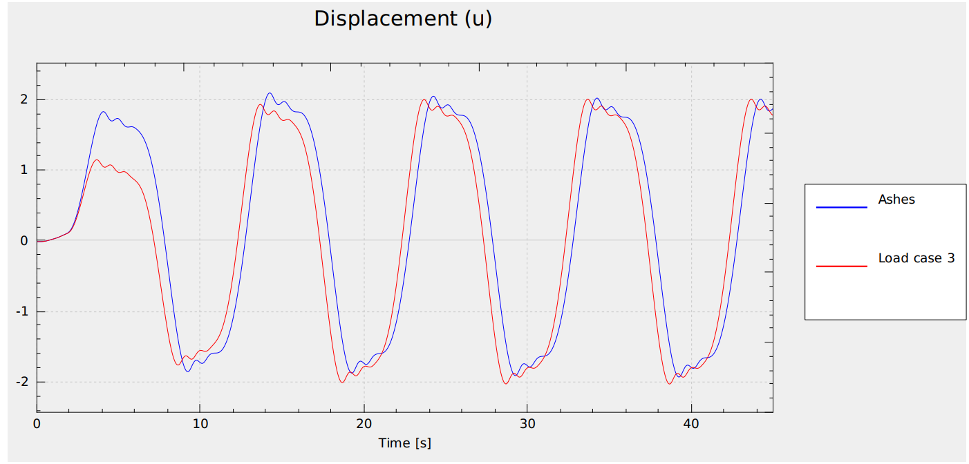
The two elastic load cases (LC1, LC2) match tightly. The plastic load cases (LC3, LC4) match closely in amplitude and in shape — same period, same flat-topped ratcheting plateau, same stabilized symmetric plastic cycle. The figure below shows the tip displacement for Load case 3 (plastic, slow): the agreement between Ashes and OpenSees is very good, with only a small offset in phase that grows slowly over the simulation. This residual phase shift is the expected signature of the concentrated-versus-distributed plasticity difference described in Section 3.1; the displacement amplitude, which is the validated quantity, is captured well throughout.
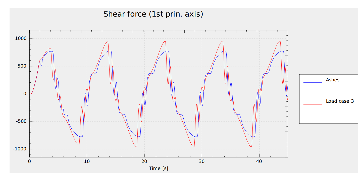
Base-element shear force (1st principal axis) for Load case 3 (800 kN, plastic regime): Ashes (blue) vs OpenSees (red). The plastic-regime divergence in base loads — lower Ashes peaks and a different waveform shape — reflects the concentrated- vs distributed-plasticity difference discussed above.
The report for this test can be found on the following link: