Fixed rotor support analytical
1 Test description
This test verifies the support that holds a fixed rotor, i.e. the boundary condition applied at the base of the rotor when the
RNA
Configuration is set to
Fixed Rotor (see
RNA). That configuration is used to model a single blade as it would be tested in a laboratory, and the support represents the rig the blade root is bolted to: either perfectly clamped, or held by a translational and a rotational spring of finite stiffness.
The model is a prismatic cantilever blade pulled by a point load at its tip. The analysis is
static and
linear, the elements are
Euler-Bernoulli, and gravity is reduced to a negligible value so that the tip load is the only load acting on the structure. Under those conditions the response is the superposition of three independent, closed-form contributions: the rigid-body translation of the base, the rigid-body rotation of the base, and the bending of the blade itself. The test asserts each of the three separately.
The test varies the
Support type and the two support stiffnesses. The following load cases are tested:
- Clamped — the base can neither translate nor rotate
- Springs, rigid — springs so stiff that the support is effectively clamped
- Springs, flexible in translation — a soft translational spring, a rigid rotational one
- Springs, flexible in rotation — a rigid translational spring, a soft rotational one
- Springs, flexible in both — both springs soft
The stiffnesses of the flexible cases are chosen so that each spring contribution is a large fraction of the elastic deflection of the blade, and the load cases therefore turn on the physics rather than on the comparison tolerance. Load cases 1 and 2 must produce the same answer, which is what tells us that the spring support degenerates correctly to a clamped one.
2 Model
2.1 Model description
The model used for this test is shown in the figure below. The blade stands along the global z-axis, and the red square at its base marks the support holding the fixed rotor:
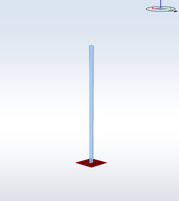
The rotor carries a single blade of the catalogue type
Timoshenko blade 6 m: a prismatic blade with a constant cross section, no twist and no prebend, of length
$$L=6\text{ m}$$
The material has an elastic modulus
$$E=2.1\cdot10^{11}\text{ Pa}$$
and the second moment of area of the cross section about the bending axis is
$$I=2.517\cdot10^{-4}\text{ m}^4$$
. This is the same blade, and the same
$$E$$
and
$$I$$
, as the
Timoshenko Blade test, whose Euler-Bernoulli case already validates the tip deflection of this cantilever against theory.
The
Hub radius is set to zero, so that the base of the rotor, which is where the support acts, is the blade root node itself. The
Tilt angle and the
Cone angle are both zero, so the blade lies in the global y-z plane and the support springs act along and about the global axes.
2.2 Loads and analysis settings
A single point force is prescribed at node 11, the tip node of the blade, in the global x-direction:
$$P=1\cdot10^{5}\text{ N}$$
The analysis is static and linear, and the elements are Euler-Bernoulli. Gravity is set to
$$g=1\cdot10^{-3}\text{ m}\cdot\text{s}^{-2}$$
which makes the self-weight of the blade negligible next to the tip load, so that the tip load is the only load in the problem. Eigenmodes are not solved.
2.3 Support stiffnesses
The five load cases differ only in the
Support type and, when it is set to
Spring, in the translational stiffness
$$k_t$$
(Support spring stiffness) and the rotational stiffness
$$k_r$$
(Support rotational spring stiffness):- Clamped: Support type = Fixed (the two stiffnesses are not applicable)
-
Springs, rigid:
$$k_t=10^{12}\text{ N}\cdot\text{m}^{-1}$$,$$k_r=10^{12}\text{ Nm}\cdot\text{rad}^{-1}$$
-
Springs, flexible in translation:
$$k_t=10^{6}\text{ N}\cdot\text{m}^{-1}$$,$$k_r=10^{12}\text{ Nm}\cdot\text{rad}^{-1}$$
-
Springs, flexible in rotation:
$$k_t=10^{12}\text{ N}\cdot\text{m}^{-1}$$,$$k_r=10^{8}\text{ Nm}\cdot\text{rad}^{-1}$$
-
Springs, flexible in both:
$$k_t=10^{6}\text{ N}\cdot\text{m}^{-1}$$,$$k_r=10^{8}\text{ Nm}\cdot\text{rad}^{-1}$$
3 Analytical solution
The tip load is carried straight through the blade into the support, so whatever the stiffness of the support, it sees a force
$$P$$
and a moment
$$PL$$
. In a linear analysis the response is then the superposition of three terms, each of which is checked on its own channel.3.1 Translation of the base
The base translates along the load direction by the support force divided by the translational stiffness:
$$u=\frac{P}{k_t}$$
This is zero for the clamped load case,
$$10^{-7}\text{ m}$$
for the two cases with a rigid translational spring, and
$$0.1\text{ m}$$
for the two cases with a soft one.3.2 Rotation of the base
The base rotates about the axis normal to both the load and the blade by the support moment divided by the rotational stiffness:
$$\theta=\frac{PL}{k_r}$$
This is zero for the clamped load case,
$$6\cdot10^{-7}\text{ rad}$$
for the two cases with a rigid rotational spring, and
$$6\cdot10^{-3}\text{ rad}=0.3438^\circ$$
for the two cases with a soft one.
Note: the sensor channel this is compared against,
Rotational displacement (rv), reports
degrees (Ashes exposes a separate
Rotational displacement (rad) family). The closed form above is computed in radians and converted before comparison.
3.3 Bending of the blade
On top of the rigid-body motion of the base, the blade bends as a cantilever under a tip load:
$$\delta=\frac{PL^3}{3EI}=0.13622\text{ m}$$
The blade deflection channels are measured against the
displaced rotor frame, i.e. against the hub position and the rotor plane as the support has left them, so that the rigid-body motion of the base is subtracted out and what is reported is the bending of the blade alone (see the note on
Support type in
RNA). This quantity is therefore
the same in all five load cases: it does not depend on
$$k_t$$
or
$$k_r$$
. Comparing it against the same closed form in every load case is what asserts that the blade-relative deflection does not move when the support goes soft.4 Results
Three channels are compared in each of the five load cases:
-
Displacement (u) of the hub node, against
$$P/k_t$$
-
Rotational displacement (rv) of the hub node, against
$$PL/k_r$$converted to degrees
-
Tip deflection (in-plane) of the blade, against
$$PL^3/(3EI)$$
The first two are read from the global node sensor at the hub. Since the hub radius is zero, that node is the blade root node, which is the node the support acts on, so those two channels report the motion the support has allowed. The third is read from the blade sensor and reports the bending of the blade relative to the displaced rotor frame.
All three are static quantities, and the pass/fail criterion used is the
static criterion (criterion 6, see
Comparison criteria): the value at the end of the simulation is compared against the analytical value. The test is considered failed if the relative error exceeds 0.5%.
The report for this test can be found on the following link: